The cellphone detecting hat band concho
This project has roots in two incidents that occurred about a year ago.
First off, we have the usual suspect - a post on the Electrical Engineering Stack Exchange.
Someone tried to build a cellphone detector, and it didn’t work. Or, rather, the simulation didn’t work. That was not a surprise, really. The circuit functions by misusing a CA3130 as an RF detector. Simulators don’t simulate unspecified behaviour, and the CA3130 is only specified to 15 MHz - not the 800MHz and more that would be needed to detect a modern cellphone.
I looked around a bit, and found one of the many sites where the CA3130 cellphone detectors are described. It turns out that even when it works the detection “range” is only a few centimeters. That’s not very impressive given the amount of circuitry and the fact it’s an active (powered) circuit.
I got to thinking about it, and decided it would be kind of nifty to make a totally passive cellphone detector. No batteries. I figured it ought to be possible to get the same range as the battery powered detectors, even without a powered circuit.
About the same time, the other incident happened - the band on my gray fedora broke. Pop! and my hat wouldn’t stay on my head.
Something inside my little pea brain joined those two incidents together, and the idea of a cellphone detecting hat band was born.
I sketched out what I wanted the hat band to look like:
| Hat band sketch |
|---|
 |
It’s not fancy. Well, I’m not a fancy kind of person.
I had it made by a small handicrafts company I found on the Internet. I’ve worked with leather before, and if it were purely a functional thing I’d have just done it myself. This isn’t just functional, though. It’s mostly decorative - it has to look good as well as work. I know my limits. Clean cut edges and neatly sewn seams are more than I’m up to.
On the other hand, if I’d have done it myself it would have been done 10 months ago instead of today. There were delays in getting the hat band made, as well as confusion that went over and beyond the problems to be expected when an American tries to tell a German what needs to be done. I mean, language problems are one thing. Completely ignoring drawings and making something completely different than asked is a whole ‘nother can of worms.
At any rate, I finally got the finished hat band so I could join it with the cellphone detector I finished like 9 months ago.
Here’s the finished hat band I finally received in the mail today:
| Hat band |
|---|
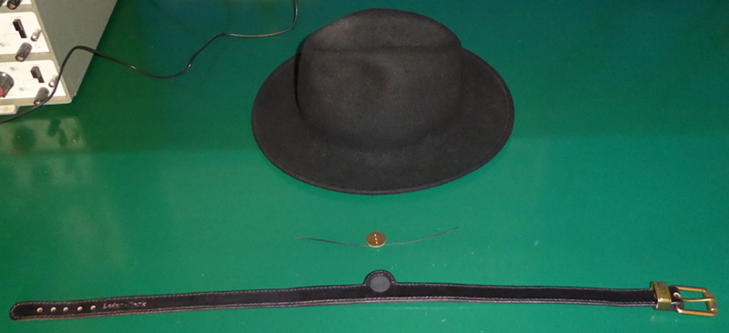 |
The buckle is bigger (and fancier) than I’d have liked, but it looks OK on the hat.
The little golden thing there is the cellphone detector. It actually detects more than just cellphones. It responds to pretty much any source of RF. The only intentionally frequency dependent parts of it are the antennas. It reacts to GSM (900MHz here in Germany) and WiFi (2.5GHz.) I don’t know how well it reacts to other cellphone bands - I only get GSM here at home. I’ll see what happens at work - I get LTE there with my phone.
I designed the circuit myself. Eurocircuits made the PCB for me, and I soldered it all together.
Here’s the circuit for the “concho:”
| Circuit diagram |
|---|
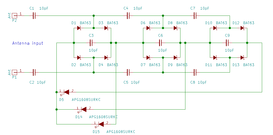 |
That’s three fullwave rectifiers, stacked to add the resulting DC voltage. It’s not (quite) a Cockcroft-Walton voltage multiplier. I’m not going to go into the difference today. It isn’t a multiplier, but it does what I need.
There’s not much to it. Bunch of diodes and capacitors, some LEDs and a couple of pieces of wire.
The BAT-63 is good to over 2.4GHz according to its datasheet, so fine for what I’m doing.
I picked the APG1608SURKC LEDs because they are very efficient (at least from what I could tell compared to many others that I checked.) Efficiency is a must because all the power there is, is what the two little antenna wires pick up.
The “range” is something like five or six centimeters for the 900MHz GSM band, less for 2.5GHz WiFi. That’s at least as good as the CA3130 circuit - and it doesn’t need batteries.
I simulated it with Qucs before I built it. I’d have used LtSpice like other folks do (even under Linux,) but I couldn’t figure out how to get Infineon’s BAT63 model into LtSpice - but I found an easy to follow example for getting Infineon’s models into Qucs.
The 10pF capacitors were arrived at experimentally with Qucs. Not sure how well the real thing matches the simulation, but it works well enough.
Getting the PCB made by Eurocircuits was a little tricky. They automatically add a production number to every board they make. The automated process kept adding it to the gold plated side because that’s where the most available space was. I finally added a note to the files, and one of their engineers moved the production number to the other side and left my gold plating in peace.
It looks like this:
| Concho front |
|---|
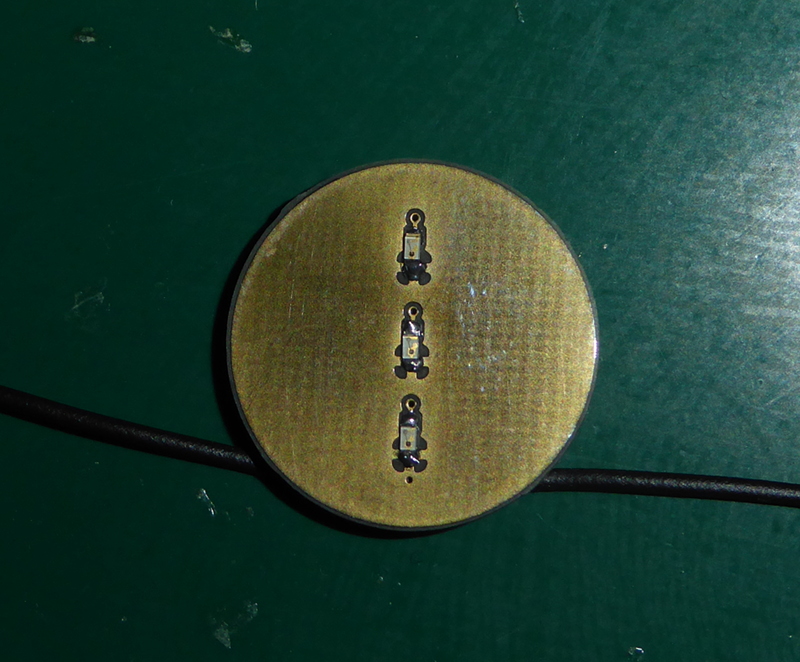 |
| That’s standard gold plating. Thin and easy to scratch. I used frog tape to mask off the areas around the LEDs while soldering - there’s no solder mask on that side (because gold,) and peelable solder mask on a one off was way too expensive. |
| Concho back |
|---|
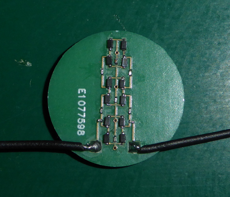 |
| Before you complain that the parts are on there a little crooked, consider that those capacitors are 0201 sized parts, and that I did them all free hand with a cheap soldering iron and no magnifying glass. |
The LEDs form a (short) bar graph. They light from the top down. Only the highest LED on - weakest signal. Highest and middle LED - stronger signal. All three LEDs on, strongest.
I didn’t make any photos when I assembled the concho itself - I hadn’t dreamed up this blog yet, so I just built it and tried it out.
I made photos today of how the concho and the hat band go together, so I’ ll show you those.
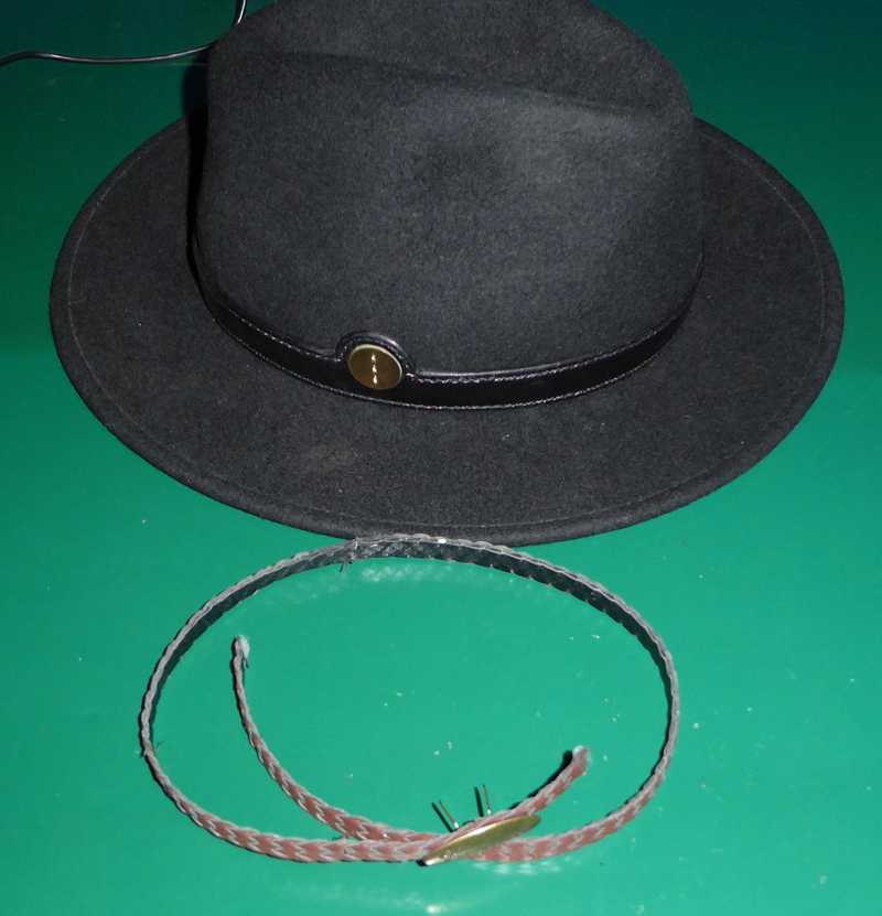
| Assembling the hat band |
|---|
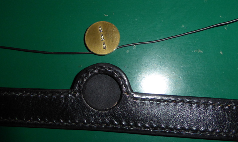 |
| There’s a hole in the thick leather of the hat band. It’s a press fit for the concho. |
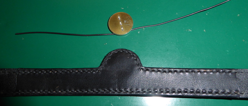 |
| Behind the opening for the concho is a thin piece of leather so the concho doesn’t just fall through. It also holds the antenna wires in place. |
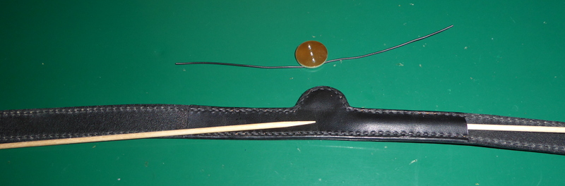 |
| I used some small wooden skewers from the kitchen to hold the back open to insert the antenna wires. Push the wires down the channels, pop in the concho, press it flat, pull out the skewers. |
 |
| All done. |
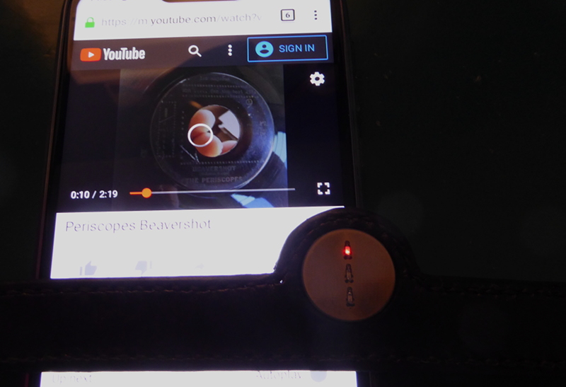
Now my hat blinks when I use my phone.
That last image was made while playing a Youtube video over GSM.
This was made using WiFi:
| WiFi powered |
|---|
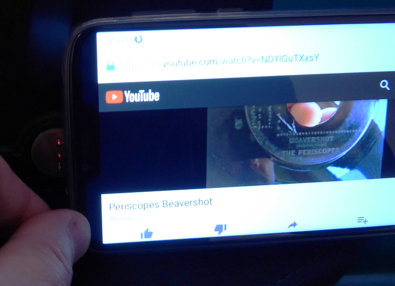 |
Oddly enough, GSM tends to make the low power LED light up really bright before it begins to light the next LED. WiFi tends to light the low power and the middle LED evenly as the power goes up. That wasn’t in any way expected, but kind of nifty. I can tell by looking at my hat whether I’m being zapped by WiFi or GSM signals.
| Finished hat |
|---|
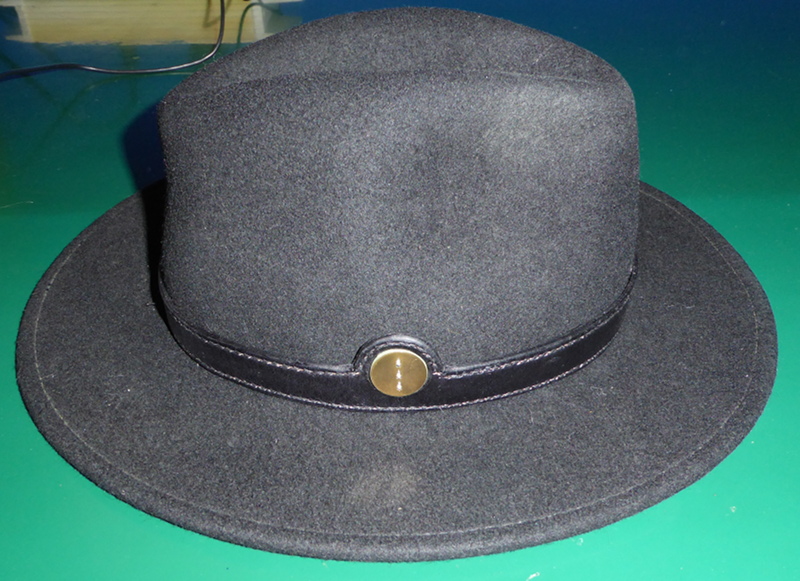 |
I don’t figure anybody out there wants to see my ugly old mug, so I’ll spare you the pain of looking at photos of me in my hat.
If you’d like to build one of your own, I’ve posted all the drawings and plans in a repository on GitHub.
FYI:
The hat band and the concho together cost way more than a new hat. I could have bought three or four new hats like the one I had (or one Stetson fedora) for what it cost me to have the hat band and the concho made. It wouldn’t have been as much fun, though. And, my wife wouldn’t have had to warn me not to blink my hat when we’re out together. I think that warning alone was worth the cost. In any case, I expect the new hat band to outlive the hat - I’ll just move it to a new hat when the time comes or when my wife buys me a Stetson.
I’ve mentioned before that I have scurrilous taste in music. If you look up the video that was playing as I made those photos and listen to it, you may be shocked. If so, it’s your own fault. You have been warned.