What's wrong with this piece of cheap junk?
Flashing lights are for the disco, not the dining room.
One LED light bulb each in the living room and the dining room have been driving me batty for the last few weeks. Mostly they are fine, but sometimes they randomly flicker and flash. Not the typical 50Hz flicker, but actual complete off then on blinks. They’ll blink, and by the time I’ve turned to look at them they’ll be shining again as though that’s all they’ve ever done. Imagine a light bulb blinking, then putting its hands behind its back and whistling innocently. Infuriating.
It was so irritating the other day that I turned them out of the socket so they wouldn’t blink anymore. Off is better than blink. Each ceiling lamp has five of the darned things - losing one each just makes the rooms a little bit darker.
I took them out this evening and tore them apart to see how they work and why they blink.
They obviously blink because they are cheaply made pieces of cheap junk, but just how does being cheap make them prone to blinking?
In the final analysis, they blink because of mechanical problems and they will die an early death because of their electrical shortcomings.
First, the disassembly.
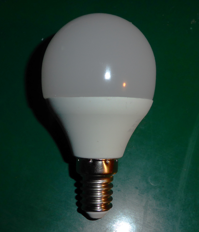
These are 5 watt LED bulbs with an E14 socket. They have a frosted plastic globe and ten white LEDs arranged on a PCB with white solder stop inside.
They look like this:
| Irritating LED bulb |
|---|
 |
I took the frosted globe off of the lamp base:
| LEDs |
|---|
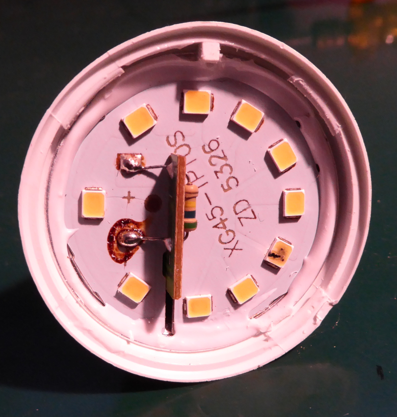 |
These are not filament bulbs. They have simple surface mount LEDs soldered to an aluminum backed PCB.
You’ll notice that one of the LEDs has a black mark on it. That LED is dead - burned out. I’ll come back to that in a little while.
There’s some glue (or maybe silicone rubber) holding the PCB in place. Whatever the white stuff around the edge is, it comes off easily at knife point (yes, I threatened its life with a wicked knife. :))
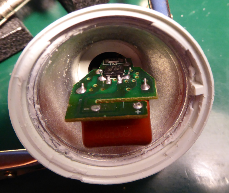
I unsoldered the two pins, then pulled the LED PCB out. Underneath that is another PCB that contains the “LED driver” (or a cheap imitation thereof.)
The driver in the base looks like this:
| Driver PCB |
|---|
 |
 |
I couldn’t get wire clippers or a soldering iron in to disconnect the driver PCB from the base, so I just brutally pulled the PCB out of the base by its roots.
I expected to break a wire or the PCB or maybe the base. What actually happened was the first clue to the cause of the blinking.
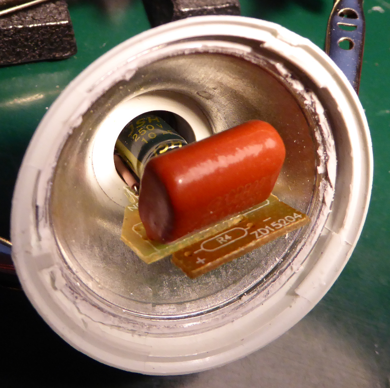
| Driver PCB - uprooted |
|---|
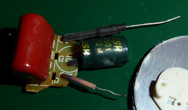 |
The wires stayed soldered to the PCB, but pulled out of the base without damage.
The wires connecting the driver to the base were simply squeezed in between the plastic base and the metal contacts that are press fit to the base.
Not soldered, not clamped, not crimped, not spot welded. Squeeze in between a piece of metal and a piece of plastic and hope for a good connection.
In the case of these two bulbs, those hopes weren’t realized. I expect they would get a bit warm, one of the wires would lose contact, and the bulb would go off. Once it cooled a little, the wire would get contact again and the bulb would light up. With a little luck, the wire would be squeezed a tad tighter and stay on. Without, it would blink again and again.
So, there’s the cause of the blinking. No electrically good connection, just a not particularly strong mechanical joint.
I mentioned above that one LED is burned out, and that I expect the bulbs to die rather short of the vaunted “long life” promised of LEDs.
That’s because I had a good look at the PCBs, and worked out the circuit.
| Bulb circuit |
|---|
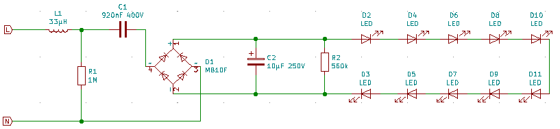 |
LEDs need a limited current to operate correctly. This usually translates to a constant current driver for high power LEDs. Indicator LEDs that operate at low current can get away with a simple series resistor and a regulated voltage. Higher power LEDs need a regulated current to work best and have a long life.
That schematic shows nothing approaching a constant current source. It is a larger version of the circuit you will see used for indicator LEDs.
The current limiting device here is not a resistor. It’s that 920nF capacitor there, marked “C1.”
At 50Hz, that capacitor has an impedance of about 3400 ohms. That works out to about 103 mA, given a peak voltage 350V (that’s the peak voltage from the 230VRMS line voltage.) That’s a smidge over 3 watts into ten LEDs that need about 3.2 volts forward voltage each. Whoops, the 5 watt rating on the bulb lied! Why am I not surprised?
At any rate, the “current regulation” of that circuit depends entirely on the line voltage being well behaved. There’s nothing in it to catch peaks or handle over voltage (which would cause over current.)
The very first picture in this post shows a dead LED. It either got too much current, or maybe the LEDs aren’t even rated for 100mA. In any case, any disturbance on the line voltage will make its way to the LEDs. Over voltage will kill them, and too much current will kill them - and they aren’t protected against any of that.
That’s about it. Poorly made mechanically, poorly made electrically. Honestly, I’m surprised that more of them aren’t misbehaving.
Those were the bulbs that came with the lamps. It looks like I’m going to have to find some better bulbs to purchase and replace them all (ouch - there’s ten to replace in all.) If I find some good ones, I’ll post pictures and descriptions as well as the manufacturer name and model number. That may take a while, though.
The ones I’ve taken apart will land in the junk box - who knows when I might need a couple of bridge rectifiers or an LED light to run on DC. I’m sure as heck not going to put them back together and use them on line voltage, though.
I intentionally didn’t show the manufacturer’s name or the model number. It is unlikely that anyone reading this will have the same bulbs - and I don’t need {random international concern} suing me for defamation (or whatever it is when you call a spade a spade and piss off the guy selling it as a “premium bovine excrement redistribution implement.”) Yeah, you can see the PCB numbers in the pictures, but you can’t search for them on google.