Voltage multipliers - Part 1 The Villard voltage doubler
Start with the simple things.
Voltage multiplier experiments - Table of Contents
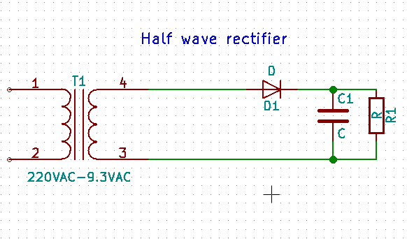
I’m going to start this part by comparing a simple half wave rectifier circuit with a simple Villard voltage doubler.
Here’s what they look like:
| Halfwave rectifier | Villard voltage doubler |
|---|---|
 |
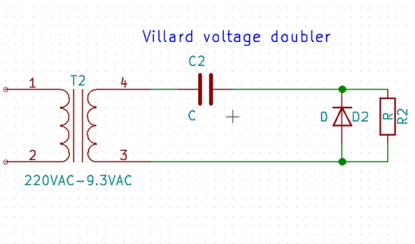 |
Almost identical, aren’t they? Exact same parts, slightly different layout and connections.
The rectifier circuit and its typical output should be familiar, but I’m going to post a picture so we can talk about it.
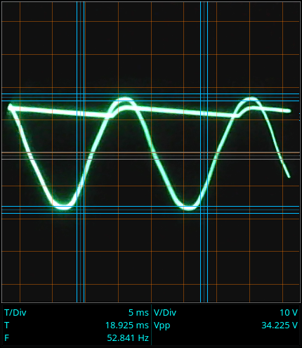
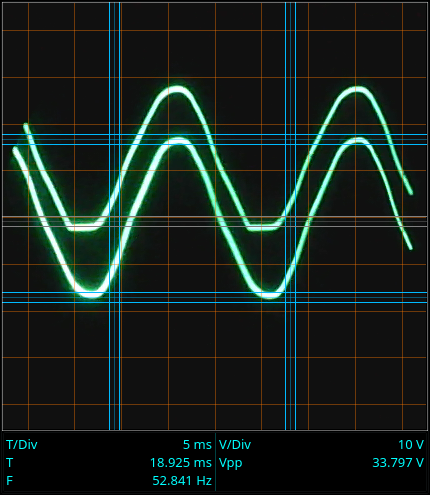
This is the output of a simple half wave rectifier:
| AC voltage | DC voltage |
|---|---|
 |
 |
Let’s see what we should be getting.
According to Wikipedia the DC voltage should be Vpp/Pi.
The cursors are showing 33V peak to peak for the AC, and 11.7V for the DC.
33Vpp/3.1415 = 10.5V DC - Close enough.
The high spots in the “DC” are at around 15V.
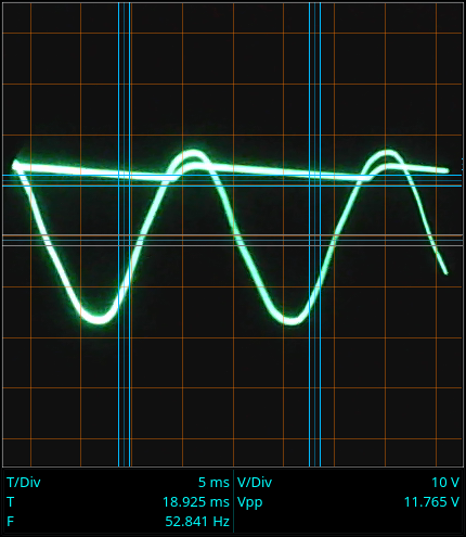
For comparison, here are the waveforms for a Villard doubler:
| AC voltage | DC voltage |
|---|---|
 |
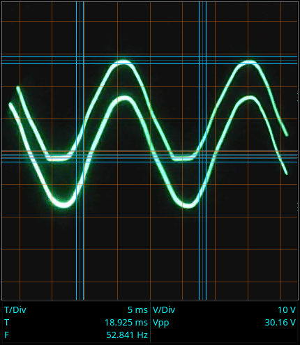 |
The output of the Villard circuit doesn’t look much like DC - that’s a disadvantage of this circuit.
On the plus side, the peaks are clearly twice as high as the (15V) peaks of the DC out from the simple rectifier. There’s about 30V peak to peak on the output of the Villard, and it is all positive.
The Villard output is just the AC offset by a DC voltage so that the AC peaks move up above the zero volt line. It still looks like AC, but there’s no negative half of the wave cycle.
The Villard output is better than nothing, but can be improved upon. The next better voltage doubler is the Greinacher circuit. I’ll look at it in the next post.