Voltage multipliers - Part 9 Failure modes
Virtually releasing the magic smoke.
Voltage multiplier experiments - Table of Contents
In the comments to the voltage multiplier table of contents, someone asked what happens when a component in a voltage multiplier fails.
I dug up the collection of voltage multipliers I built two years ago when I first wrote the series on voltage multipliers, but I couldn’t find the little transformer I used with them. Poof. Gone. Disappeared into thin air.
No matter. There are simulators.
I used to use Qucs, but I’ve been trying to get friendly with LTspice. I’ll be using LTspice to test the failure modes in a three stage Cockcroft-Walton half wave multiplier.
| Test object |
|---|
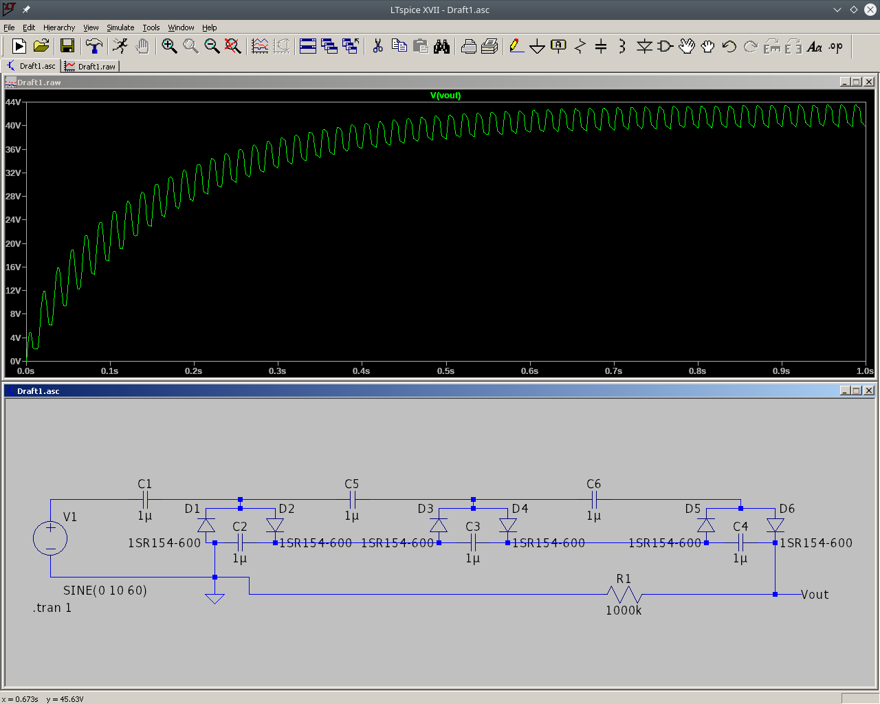 |
I’m using 1SR154-600 diodes in this circuit for a very good reason: My copy of LTspice doesn’t seem to contain a model for the common 1N4001 rectifier diode. I picked the 1SR154-600 by taking the first diode in the list that looked like it would be somewhat like a garden variety 1N4001.
The simulation there shows the normal power on response of a voltage multiplier.
What happens when a capacitor or diode fails depends on which diode or capacitor fails.
There are two kinds of capacitors:
- Coupling capacitors that allow the DC voltages to be stacked. (C1, C5, and C6.)
- Smoothing capacitors that make the DC look more like DC and less like AC. (C2, C3, and C4.)
There are also two kinds of diodes:
- Clamps that work with the coupling capacitors to add the voltages together. (D1, D3, and D5.)
- Peak detector diodes that work with the smoothing capacitors to make a smooth DC. (D2, D4, and D6.)
The components can fail in one of two ways:
- Open
- Short
Let’s take a look at all the combinations.
Coupling capacitor failure
If a coupling capacitor fails open, you get something like this:
| Coupling capacitor open |
|---|
 |
I’ve just removed a wire, but the same thing would happen if the capacitor itself were open circuit.
That’s the voltage from the stages before the broken capacitor. You lose all the voltage the later stages would have provided. It still works, and nothing bad happens, but the output voltage is much lower than it should be.
| Coupling capacitor shorted |
|---|
 |
You lose the voltage that you would normally gain from the stages after the short. You also lose a good bit of the smoothing that would normally take place. The result is that you have the fully smoothed DC from the stages before the short. For the stage with the short, you have the additional voltage but without the smoothing.
Still no real catastrophes - lower output with more ripple, but nobody gets hurt.
Smoothing capacitor failure
If a smoothing capacitor fails open, you just get more ripple:
| Smoothing capacitor open |
|---|
 |
The peak output voltage stays the same, you’ve just got a lot of ripple. Again, nothing bad happens.
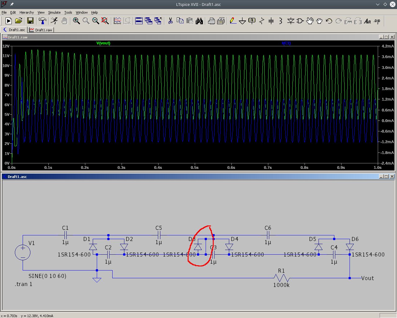
If a smoothing capacitor fails short, you get this:
| Smoothing capacitor short |
|---|
 |
The only thing keeping the diodes from going up in smoke at this point is C1 and the load. The current is limited by the impedance of the capacitor and the resistance of the load. With C3 shorted, there’s a direct path from C1 to the output. If your capacitors are low impedance at the AC frequency you are working with, you can supply a lot of current to the load. If the load is also low resistance, then you’ve got a bad situation on hand - crash, bang, smoke.
Clamp diode failure
An open clamp diode causes a loss of output voltage, but doesn’t greatly affect things at all.
| Clamp diode open |
|---|
 |
The output reaches the same peak as if the multiplier had one stage less, but it can’t hold the output at that peak. It slowly drops back to just the output level of the multiplier stages before the open diode.
A shorted clamp diode is a bad thing.
| Shorted clamp diode |
|---|
 |
As with a shorted smoothing capacitor, the only thing preventing a catastrophe is the impedance of C1 and the resistance of the load.
Peak detector failure
An open peak detector is pretty much just like an open clamp diode.
| Open peak detector |
|---|
 |
The output is lower than expected, there’s more ripple, and the output rises to a peak then sinks to somewhat less than the voltage you would expect from a multiplier with one less stage. Nothing bad happens, you just don’t get the voltage you wanted.
A shorted peak detector is nearly as bad as a shorted clamp diode.
| Shorted peak detector |
|---|
 |
The current isn’t quite as high as for a shorted clamp diode, but it is still much higher than it ought to be. As in the other cases, it’s C1 and the load that prevent a total catastrophe.
Short on C1
The first capacitor in the circuit is sort of special. If it shorts out, your multiplier will draw absolutely stupid amounts of current.
Here’s what it looks like when C1 is shorted:
| C1 shorted out |
|---|
 |
The lower resistance C1 has when shorted, the worse it gets. I’ve shorted it with a 1 ohm resistor so that I could measure the current. The scale says it is drawing pulses of current at over 8 amperes.
In real life, the transformer probably can’t deliver that much current. It’ll still get hot, and probably quit (if it has a built in thermal fuse) or catch on fire (if there’s no safety fuse built into the windings.)
Shorted load
Don’t short circuit the output of a voltage multiplier. C1 is all that’s between you and a horrible mess if you short circuit the output.
Here I’ve changed the load resistor fom 1 Mohm to 1 ohm. I’ve also increased C1 considerably.
| Shorted load |
|---|
 |
The only thing limiting the current is the impedance of C1. You normally want the impedance to be low - high impedance means you can’t get much current out of the multiplier.
When you have a low impedance multiplier, a short circuit at the load can cause a lot of current to flow through the multiplier, damaging the diodes and the capacitors.
Summary
- Parts that fail open are a nuisance but won’t cause any additional damage.
- Depending on where they are, parts that fail short can either be a nuisance or can cause damage to further parts of the circuit.
- If the first coupling capacitor fails short, it can destroy your AC source and/or the rest of the voltage multiplier circuit.
Don’t take chances while working with this stuff.
- Work with low voltage multipliers until you have a good understanding of how multipliers work. The low voltage lets you easily take measurements that would be difficult to make with a high voltage multiplier operating at thousands or tens of thousands of volts.
- Use good quality parts rated for the voltages and currents you are using. A failure can be anything from a nuisance to a catastrophic event depending on which part fails and how it fails.
I used a small 9VAC transformer in the earlier parts of this series (when I was building the circuits live.) I’ve stuck with the low voltage even in the simulations. The circuits work the same, no matter the voltage - they are just less likely to kill you at low voltage.