HowTo: Solder by hand - Repair an Android headset
Everything it takes to replace a broken Android headset plug (4 pole CTIA.)
HowTo: Solder by hand - Table of Contents
I’ve been playing with Android headsets quite a bit lately, chopping them apart then putting them back together for various purposes. Along the way, I promised to show how to tin and solder the fine wires typically found in headset cables. That ties in quite well with a promise I made earlier in the “HowTo: Solder by hand” series - namely, to extend the series any time I run into an interesting soldering task.
Headset cables can break in different spots, but the most common cause is a broken wire in the plug. It is also the absolute worst case - you have to replace the plug and figure out what wire goes where with nothing but a broken headset as a guide. I’ll explain how to replace the plug. The soldering techniques can also be used on other parts of the headset.
So, shooting two birds with one stone (fulfilling two promises with one post,) here’s a description of how you can repair a broken 4 pole CTIA headset plug (Android headset.)
Warning:
This will be a long post. It covers a lot of details and includes a lot of photos. The length will look frightening, but like most things that have to do with soldering, it goes much quicker than the length suggests.
Steps
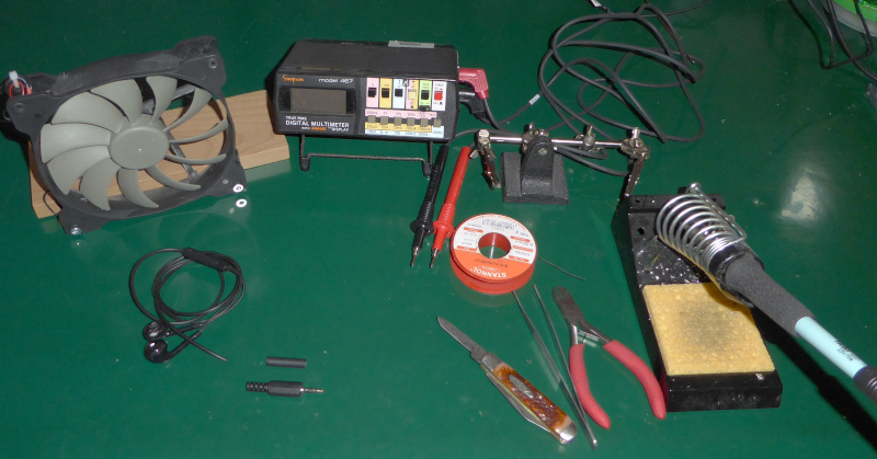
Here are all things it’s going to take to show you how to replace a CTIA 4 pole headset plug:
- Tools
- Replacement parts
- The plan
- Prepare the headset
- Tin the wires
- Map the connections
- Connect the new plug
Tools
There’s two parts to this job - figuring out which wire goes where, and connecting the wires to the new plug.
You’ll need the following tools:
- Soldering iron and solder
- Side cutters
- Pocket knife
- Third hand
- Tweezers
- Pliers (not shown in photo)
- Fume extractor or fan
- Multimeter
- Paper and pencil
The meter and the paper and pencil will be needed to figure out how to connect the new plug. The other tools are for the actual work of replacing the plug.
Part of the job involves burning the insulation off of the fine wires in the headset cable. They can’t be stripped by any mechanical means. Burning the insulation off produces fumes that you don’t want to breath too much of - you need a fan or fume extractor to keep the air clean.
| Tools |
|---|
 |
Replacement parts
You’ll need a 4 pole CTIA plug to replace the broken one. The truth is that often times it is just a wire broken off inside the plug. The problem is that the insulation on the plugs is usually injection molded onto them. That works much better and is more reliable than the screwed on covers of the replacement plugs, but you can’t remove and replace the molded insulation.
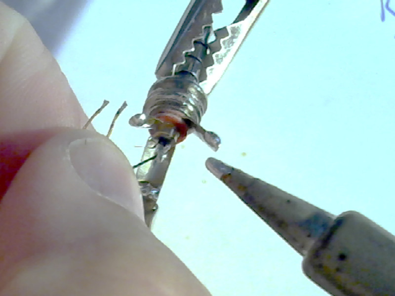
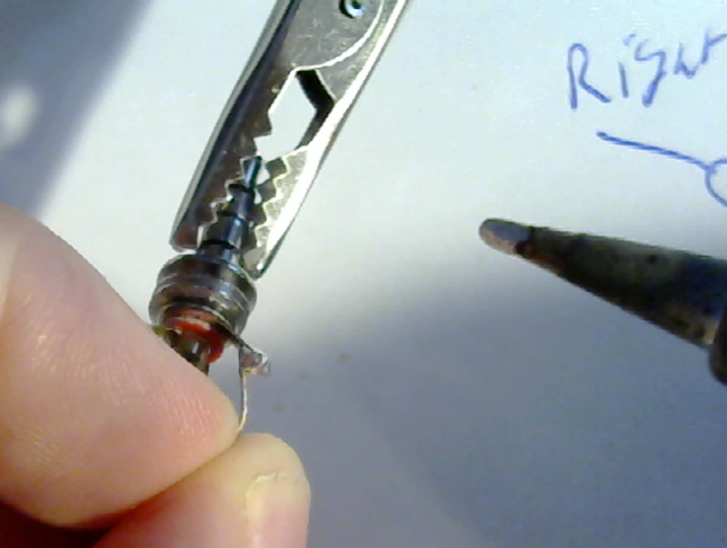
The replacement plugs can be made in different ways:
| Replacement plugs |
|---|
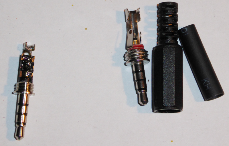 |
The one on the left there has been used for experiments - it looks rather ratty, and I’ve long since lost the insulating cover.
I’ll be using the one on the right to replace the bad plug on a headset. I bought several like it the other day, and I have the covers as well as the heat shrink tubing that came with them.
The plan
I’m going to explain how to remove the old plug, determine which wires belong on which pin, and then finally how to solder things together.
The “which wire goes where” part has been the cause of many questions on the Electrical Engineering Stack Exchange. They don’t usually get a good answer. There is no answer except “measure it and see,” and nobody explains in detail just how you do that.
The soldering part is the reason this post belongs to the “HowTo: Solder by hand” series. It’s a bit tricky. The correct solution isn’t obvious to beginners, either.
Prepare the headset
The first step is brutal: Cut the existing (broken) plug off of the headset. Leave a couple of centimeters (an inch or so) of the cable attached to the plug. That makes a good practice piece to try out stripping the insulation and tinning the wires.
My headset isn’t broken - it is missing a plug because I used it as an example of how to make something else out of a headset. I’d rather fix it than throw away the left over pieces.
You can see it in the picture up there with the tools. It’s coiled up in the lower left corner with a replacement plug beside it.
Stripping the cable:
With the plug removed, the next step is to remove the outer insulation from the cable so that you can get to the individual wires inside.
I use my pocket knife for this step. I have a knife with two blades. On is very sharp, the other is (intentionally) dull. It is easier to strip wire with a dull blade than with a sharp one. With a sharp blade, you run the risk of cutting the wire in two - and the risk of cutting into your thumb.
The idea is not to cut the insulation off of the cable. The idea is to nick the outside of the insulation, then pull it until it breaks. This avoids the risk of cutting or scraping the wires inside the cable.
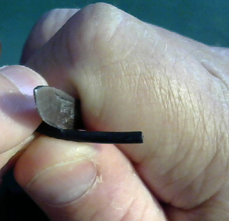
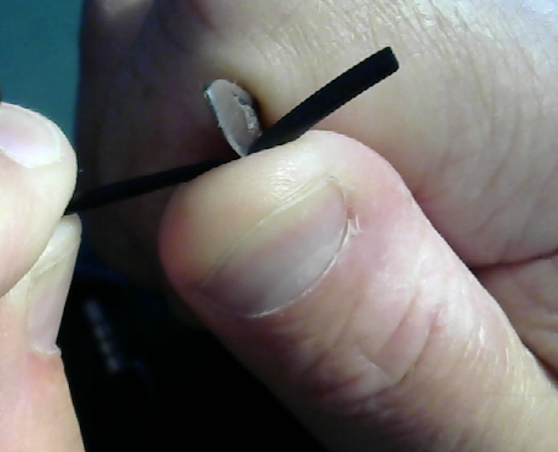
The first step is to “score” the insulation all the way around at about 1 centimeter (half an inch) from the end:
| Score the insulation |
|---|
 |
 |
Hold the wire between your thumb and the knife blade, then pull the blade across the insulation in a cutting motion. Since the blade is dull, it won’t cut into the insulation. Press the knife into the insulation while pulling the blade across it to make a sort of a groove in the plastic - but do not cut the plastic.
Do that all the way around the cable. It doesn’t matter if the grooves are all perfectly in a ring around the cable. They need to be close (1 millimeter maybe 1/16 inch) but it doesn’t matter much if the groove wiggles around the cable. Check the second picture there to see what I mean.
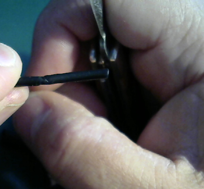
With the insulation scored all the way around, you can pull it off.
| Remove the insulation |
|---|
 |
Move the knife blade towards the free end, maybe 5 millimeters (3/16 of an inch) from the scored line. Press the cable hard between your thumb and the knife blade and pull the blade and the insulation towards the free end.
The insulation will stretch. You may need to let go and move the knife blade back closer to the scored line. Keep pulling until the insulation breaks.
It will look something like this:
| Cable insulation removed |
|---|
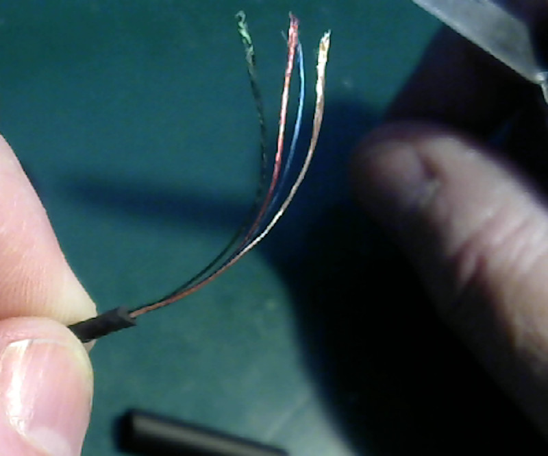 |
Mine ended up a little long - stick to the measurements given and yours should turn out better.
Now you need to trim the wires to the correct length. It doesn’t take long wires to connect the plug. In fact, if your wires are too long it will make it harder to replace the plug. It is hard to get all of the wires in place and in the shell if the wires are too long.
You only need about 1 centimeter (about 3/8 of an inch) of wire to connect the plug.
| Trim the wires |
|---|
 |
Use your wire cutters (or a pair of fingernail clippers) to clip the wires to 1 centimeter.
Do not fiddle with the wires. They are made of fine strands of copper wire insulated with lacquer (paint.) The strands are wrapped around a string for strength. If you fiddle with the wires, the strands will come unwound from the string and you will have a hard time getting the strands back together.
You must tin the wires now, before the strands unwind.
Tin the wires
Here’s where you really need the fume extractor or fan.
This is the first tricky part of the whole process. You cannot use any kind of mechanical wire strippers to remove the insulation from the wires without damaging them. You can’t scrape those fine strands clean without scratching or cutting them - and a scratch is as bad as a cut because the strands will break any where they are scratched.
The solution used in factories is a solder pot. That’s a heated ceramic pot with molten solder in it. You just dunk the tips of the wires in the solder and it melts the lacquer off and tins the strands (making them stick together) all in one step.
I don’t own a solder pot and I don’t expect you do, either.
I do have a soldering iron, though - and so do you. A soldering iron can “pinch hit” for a solder pot. It isn’t as quick and easy as with a solder pot, but it works the same way.
Here’s how to tin those fine wires with a soldering iron:
Turn up the temperature on your soldering iron. You’ll want it way over the normal temperature that you use for soldering. Turn it up to 350C or so (about 670F.) The idea here is to be hot enough to melt and burn the lacquer.
Get a big blob of solder on the tip of the iron. Leave the solder wire sticking up from your work table so that you can melt more solder onto the tip without having to touch the solder wire with your hands. You will be using both hands for other things.
| Big blob of solder |
|---|
 |
That blob is your “solder pot.” You’ll need to “refill” it from time to time from your roll of solder wire, so keep the solder wire handy.
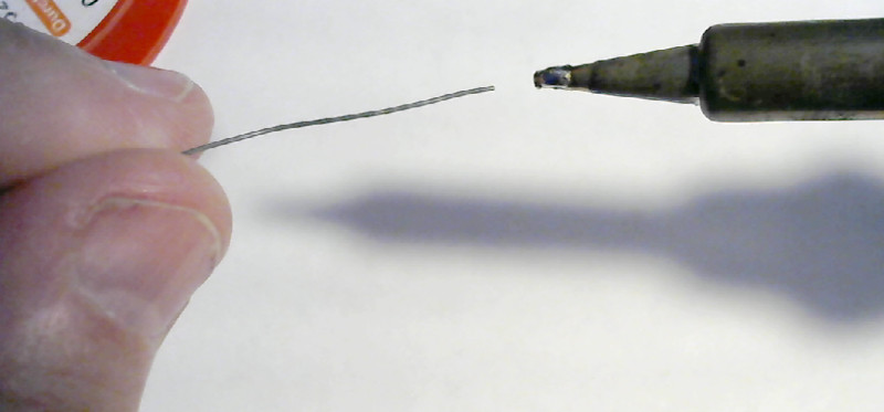
Now, poke the point of one of the wires into the blob. Use the point because the ends of the strands are already bare and will help heat the lacquer from the inside. You’ll end up with a silverly spot of solder on the very tip of the wire - with all of the strands stuck together because the string melted inside the copper strands.
| Tin the tip |
|---|
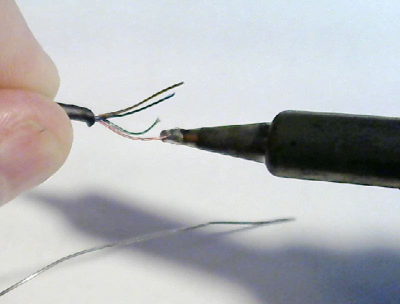 |
Now stick the wire in so that you get a couple of millimeters (1/16 inch) of the wire in the solder. Move the wire back and forth - pull it back so that just the tip is in the solder, then push it slowly in so that the last couple of millimeters are in the solder. Add fresh solder as you go along. The lacquer will melt and burn, getting impurities in the solder and using up the flux. You may need to flick the blob off and make a new one as you go.
| Tin the wire |
|---|
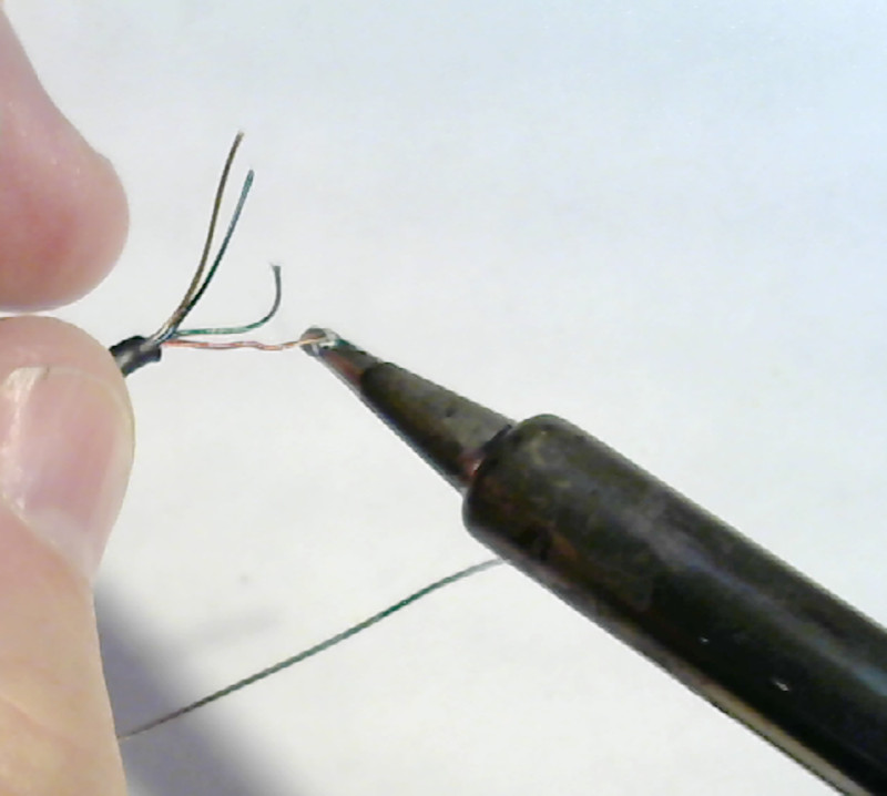 |
Do all of the wires the same way.
| Tin all of the wires |
|---|
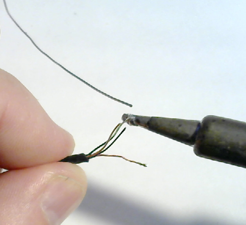 |
Note how the solder wire is standing there right where I can push the tip of the iron onto it to refresh the solder as I am working.
Here’s what it should look like when you are done:
| All wires tinned |
|---|
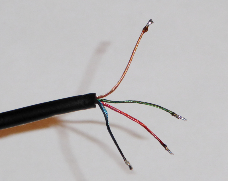 |
All the strands are still wrapped around the strings. Nothing has come unwound. There’s a small blob of melted/burned lacquer on each wire near the tinned end, but that won’t bother anything.
Turn the temperature of the soldering iron down. You can even turn it off for now. You won’t be needing it while you are using the multimeter.
Map the connections
With the wires all tinned, you can start with the next (slightly) tricky part.
All of the wires have colored insulation (counting “transparent so you can see the color of the copper wire” as a color.)
The problem is that there’s no standard color code telling you which wire is what. Every manufacturer does it their own way.
You will have to figure out what each wire is for. This is where the multimeter and the pencil and paper come in.
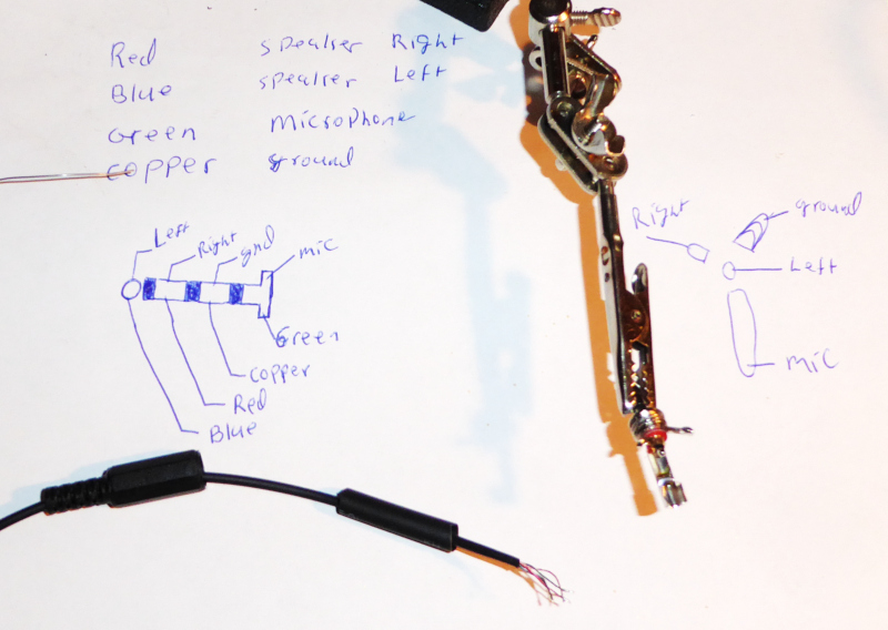
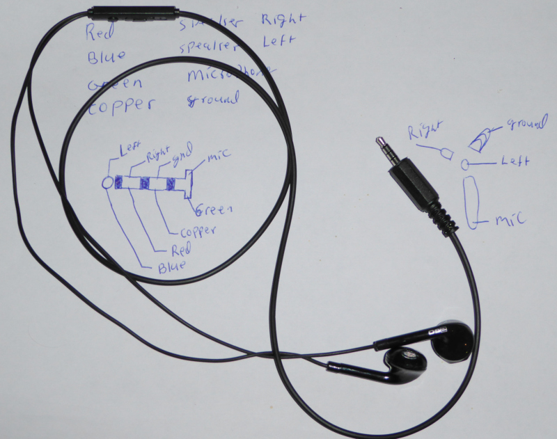
Write down a list of the wire colors.
Here’s mine:
| Wire colors |
|---|
| Red |
| Blue |
| Green |
| Copper |
Here are the functions of the four wires in a headset:
| Wire functions |
|---|
| Earphone right |
| Earphone left |
| Microphone |
| Common (ground) |
The trick here is to match those four colored wires to the four functions.
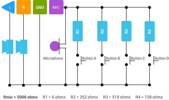
Common is called “common” because the other three signals all depend on it.
Each of the earphones is connected to common and to one of the other wires. Earphones have a resistance of less than a couple of hundred ohms.
The trick to finding which wire is for what is to measure the resistance between pairs of wires until you find a low resistance (less than a couple of hundred ohms.) One of the two then has to be the common wire.
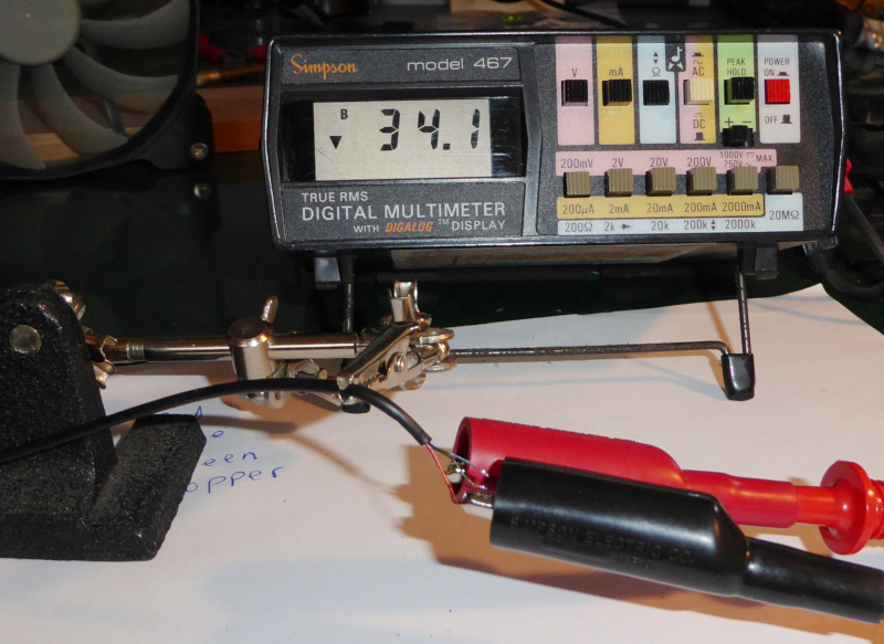
Turn on your multimeter, and set it to “Beep” or “Buzzer” or use the lowest resistance range. Touch the probes together. That “Beep” or “Buzz” is what you want to hear during the following test. If you don’t have a “Beep” function, just look for resistance values below 200 ohms. My earphones turned out to have a resistance of about 34 ohms.
| Finding the earphone connections |
|---|
 |
Here’s how you assign functions to the colored wires:
- Pick one wire and connect it to the negative terminal (black probe) of the multimeter.
- Connect the red probe to one of the other wires.
- If the multimeter doesn’t beep (or shows a high resistance,) move the red probe to another wire.
- Repeat until the multimeter show a low resistance or it beeps.
- If you try all three and nothing beeps or shows low resistance, move the black probe to one of the other wires and repeat the above steps.
- Repeat the above steps until you find two wires with low resistance between them.
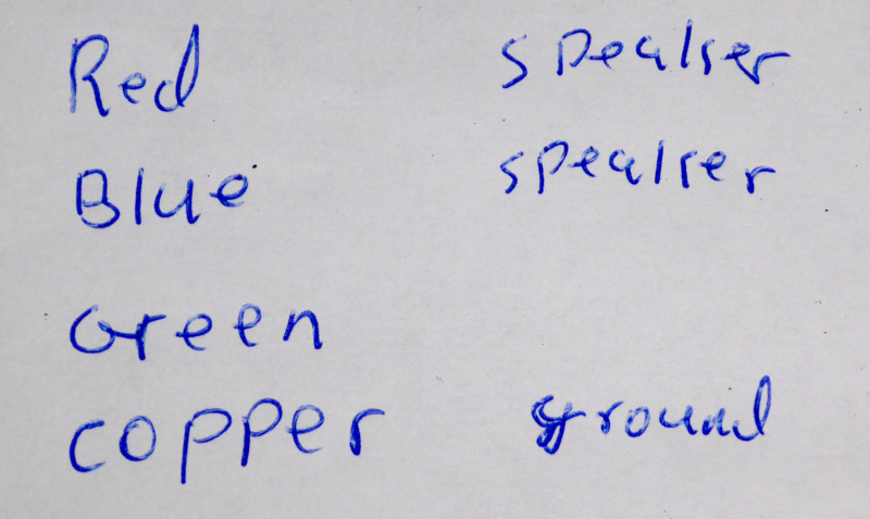
At this point, you’ve found an earphone and the common.
Take note of which colored wire you have connected to the black and the red probes.
- Leave the black probe connected and test the other two wires by connecting them to the red probe.
- If neither of them beeps or shows low resistance then the wire connected the black probe is the earphone and the wire you originally had connected to the red probe is ground. Connect the black probe to the wire you originally had connected to the red probe. Take note which wire is ground and which wire is the earphone.
- Test the other two wires and find the other that beeps. You now have both earphones and the ground identified.
| Earphones identified |
|---|
 |
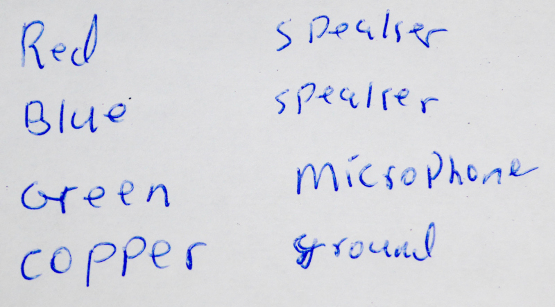
When you have the earphones and the ground identified, the wire left over is the microphone.
| Microphone identified |
|---|
 |
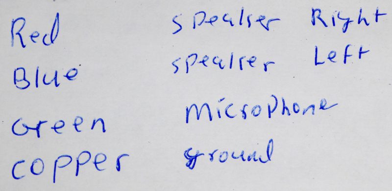
Some headsets have the earphones marked “Left” and “Right.”
Identify “Left” and “Right” by putting each earphone in the correct ear. Connect the common to the black probe of the multimeter and touch the red probe to one of the earphone wires.
The earphone whose wire you touch with the red probe will make a noise. Note which ear you heard it in, and which wire color it was. With one earphone identified, you know which side the remaining earphone belongs to as well.
| Left and right identified |
|---|
 |
Now we need to figure out which wire goes to which connection on the plug.
That is standardized. Check out the Android 3.5 mm Headset: Accessory Specification
You will find this sketch in those specifications:
| Android headset connections |
|---|
 |
Combining the Android specifications sketch with the wire color and function table you made, you will come up with a sketch like this:
| Wire colors to plug pins |
|---|
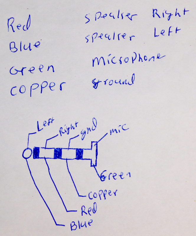 |
One last bit of sleuthing and you’ll be ready to solder the new plug onto your headset.
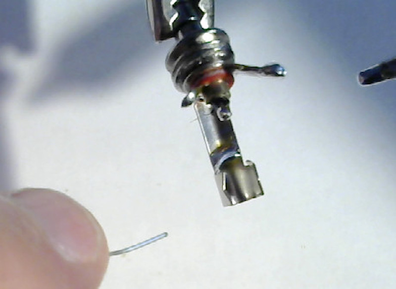
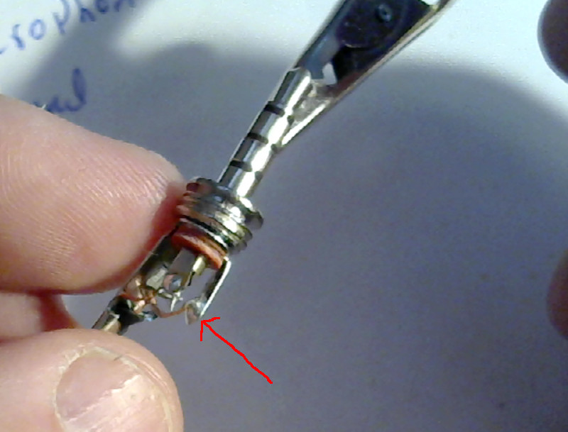
The solder tabs of the plug will look something like this:
| Plug solder tabs |
|---|
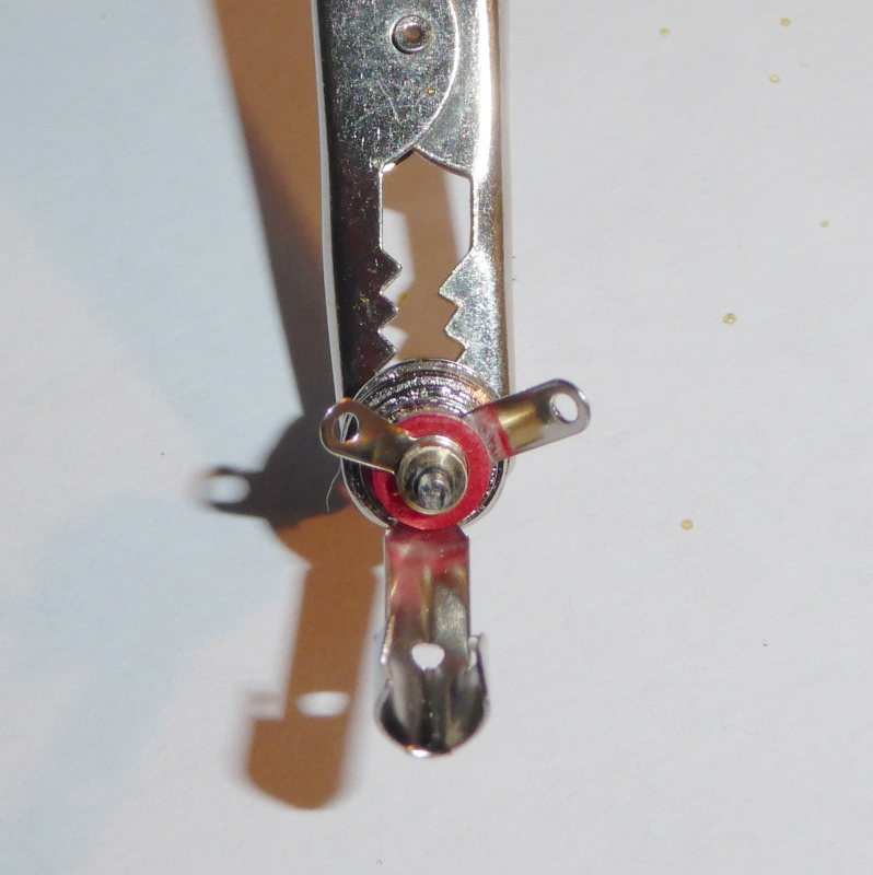 |
Draw a sketch of the solder tabs, then use your multimeter to find out which pin (or ring) on the plug goes to which solder tab.
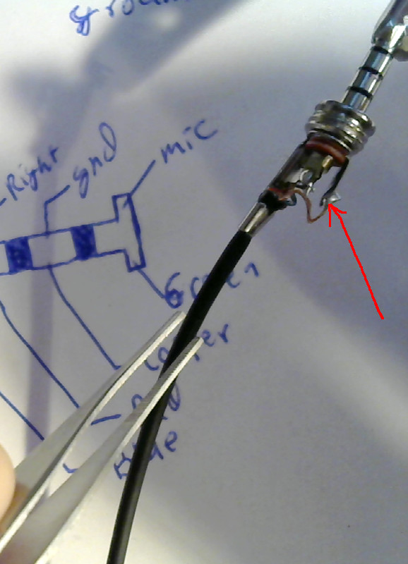
Mark the solder tab sketch with the wire colors so that you know which wire to attach where:
| Wire colors and solder tabs |
|---|
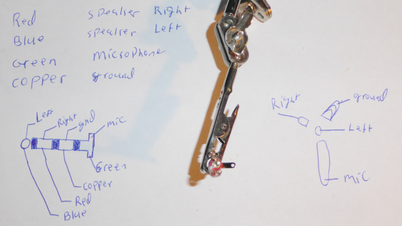 |
I marked mine with the function and kept having to look up the wire colors from the chart. It is easier to mark the colors.
That was a lot of text to read and lots of photos. It doesn’t really take that long to do it. A few minutes work and you’ll have the measurements and sketches made.
Connect the new plug
With all of the preparation done, it is finally time to do some soldering.
Remember: Use the tables of wire colors and connections that you made. My charts probably won’t work with your headset.
First, put the shell and the heat shrink tubing over the headset cable:
| Shell on the headset cable |
|---|
 |
Make sure you have the shell the right way around, then push it and the heat shrink tubing (if you have it) down the cable out of the way (towards the earphones.)
Tin all of the solder tabs on the plug:
| Tin the solder tabs |
|---|
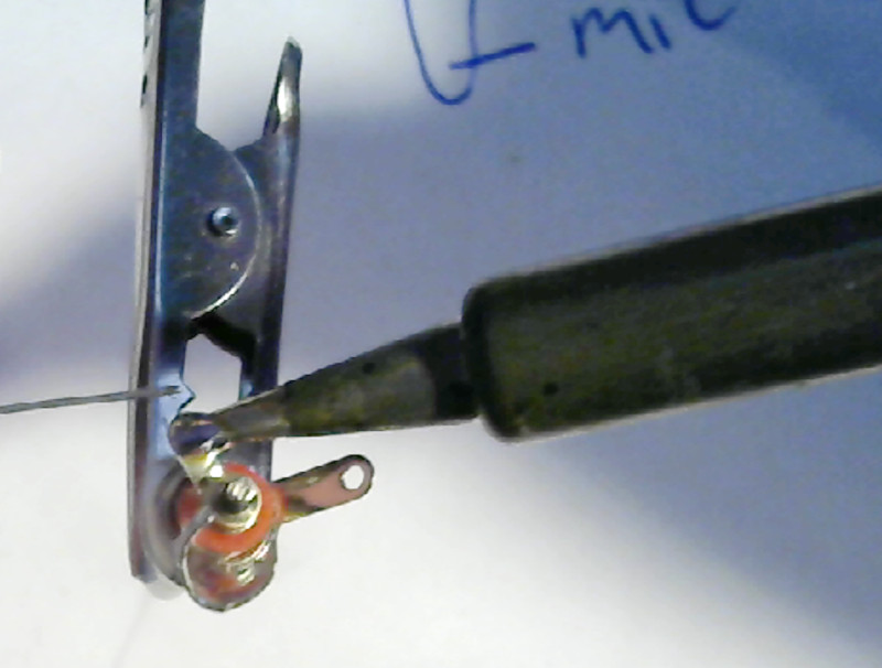 |
 |
 |
 |
Ignore the holes in the solder tabs - we aren’t going to use them. People will tell you that solder has no strength so you should wrap the wire through the holes for mechanical strength. The fact is that the wires don’t have any strength, either. Besides that, there’s not enough space inside the plug to wrap the wires. We’re just going to solder the wires flat to the tabs.
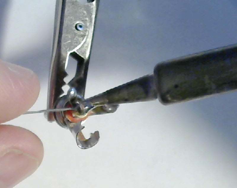
Start with the tab furthest from the plug tip, then work your way forwards. Connect the wires such that you never have to cross an already connected wire to solder another one.
| Start at the back |
|---|
 |
| Work your way forwards |
|---|
 |
 |
| All connected (but not done) |
|---|
 |
At this point you should plug the headset into your phone and make sure it works. Make a phone call, listen to some music. Make sure that the microphone works and that the earphones match “Left” and “Right” (if your earphones are marked.)
If it doesn’t work, check your soldering. Make sure you followed the tables and charts you made. If things are soldered correctly and you followed the sketches you made, go back and make sure that you decoded the wiring properly.
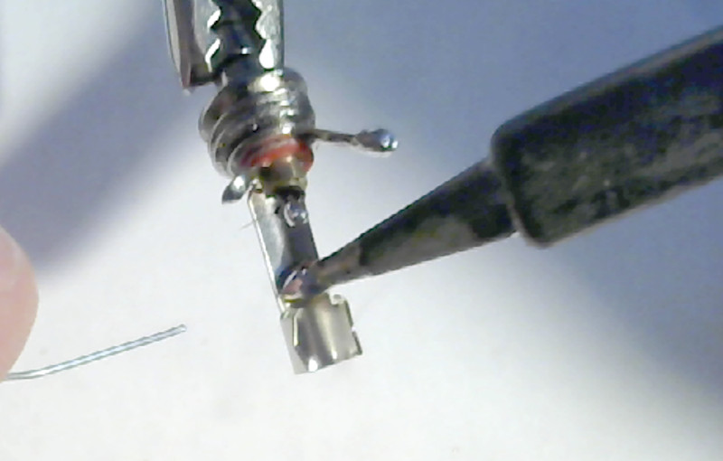
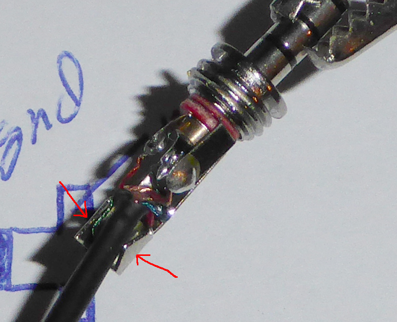
Once it is working properly, fold the tabs over so that they will fit inside the shell and the heat shrink tubing.
| Tabs in position |
|---|
 |
I had to clean up some of my solder joints at this point. There was too much solder on some of the tabs. The big solder blobs would have caused short circuits when the plug was assembled. You want flat, smooth joints with as litle solder as possible.
| Clean up |
|---|
 |
 |
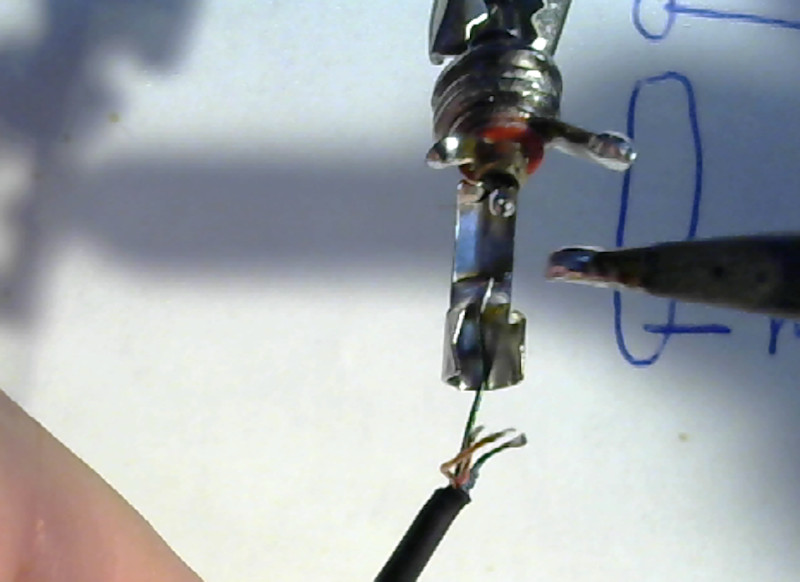
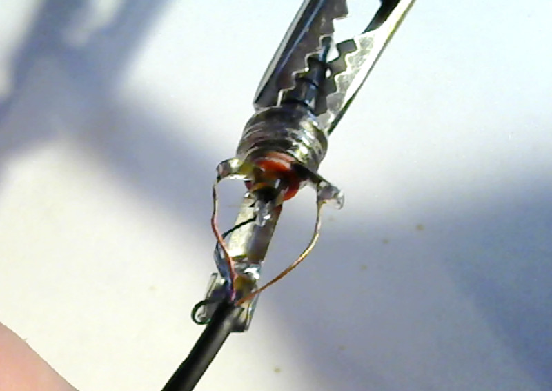
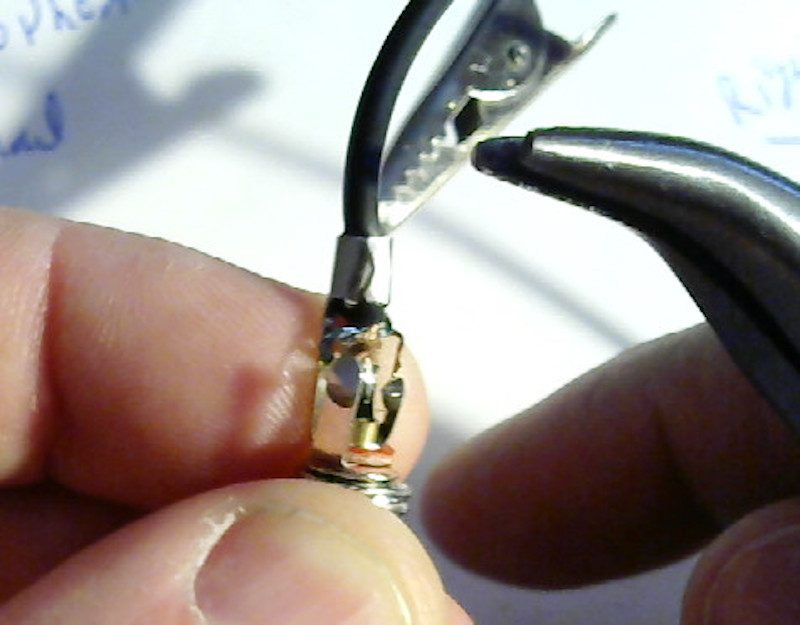
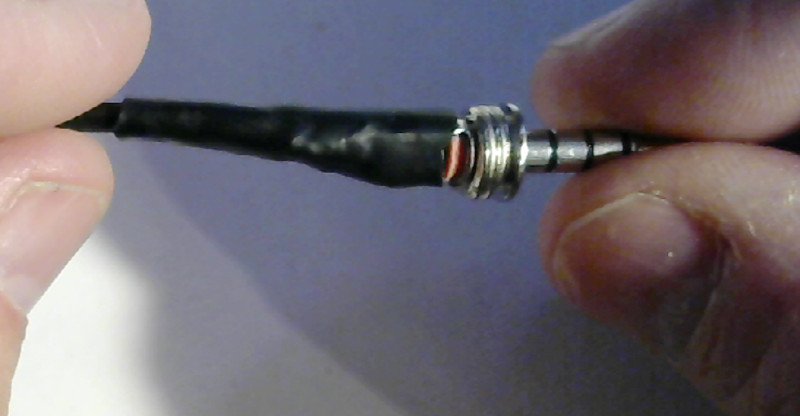
When the tabs are bent into position and no short circuits are possible, push the insulated part of the cable into the strain relief jaws of the plug.
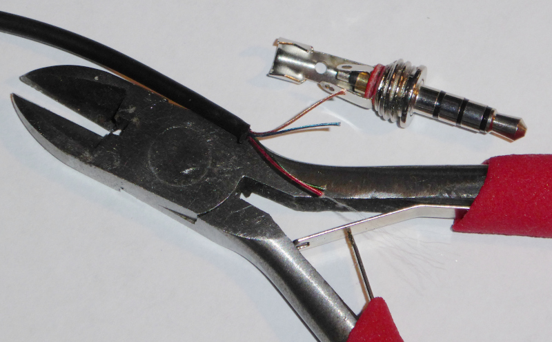
The “strain relief jaws” are the two tabs marked in red:
| Strain relief jaws |
|---|
 |
You want a couple of millimeters of insulation jutting into the space between the jaws and the other tabs of the plug.
Use your (small) pliers to crimp the strain relief jaws on the insulation of the cable:
| Crimp the strain relief |
|---|
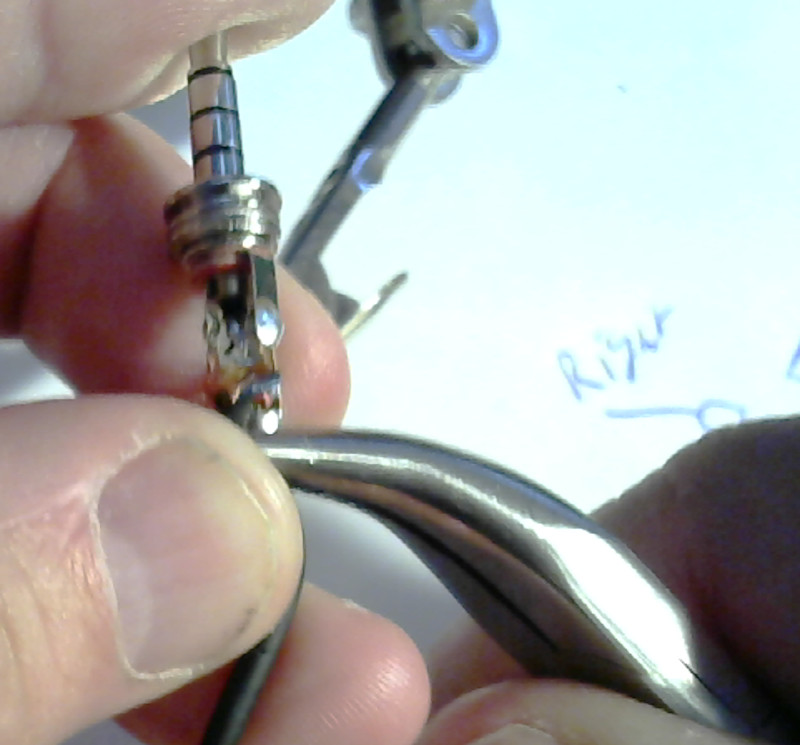 |
This is also a bit tricky. You want to squeeze the “jaws” onto the insulation tightly enough to hold, but not so tight they cut through and into the wires. Getting it right might take a try or two. If it is too loose, the cable may work its way out when you are using the headset. If you get it too tight, the jaws may cut through the cable while you are using it.
It should look like this when you are done:
| Crimped strain relief |
|---|
 |
Note the insulated part of the cable in the space between the jaws and the solder tabs.
If you have heat shrink tubing, push it forward over the solder tabs and use the tip of your soldering iron to heat it and make it shrink:
| Shrinking the heat shrink tubing |
|---|
 |
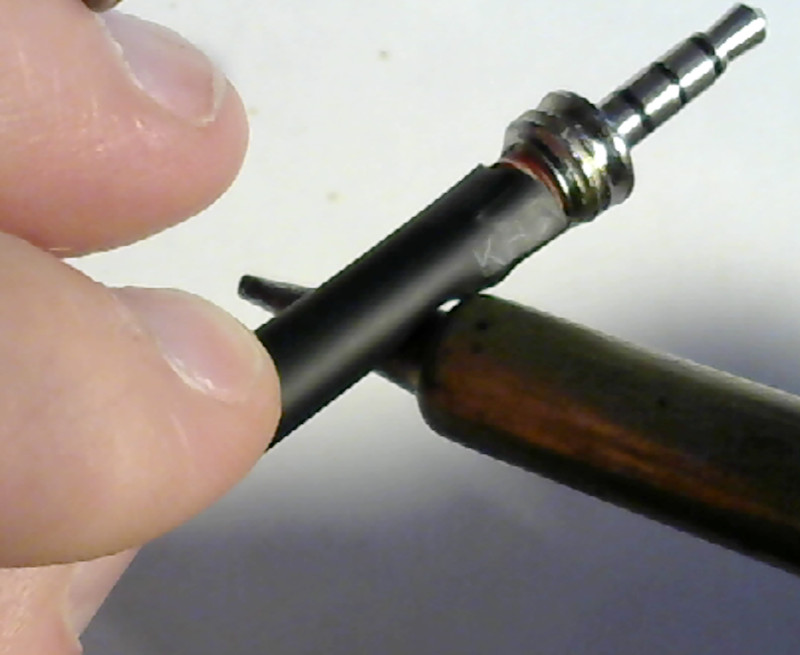 |
 |
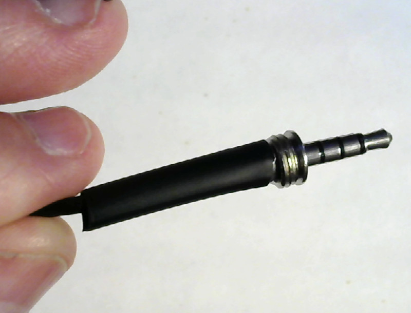
Now push the shell forward and screw it onto the plug:
| Closing the shell |
|---|
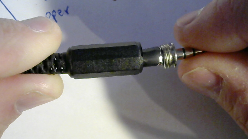 |
That’s it.
| Done |
|---|
 |
Plug it into your phone and give it a try. Make a call, play music, whatever. If anything doesn’t work right, open it up and try again - you know what it all looks like in there.
The replacement plugs won’t hold as well as the original injection molded plugs. Once you’ve repaired a headset, you can expect it to break again. If you can, be a little gentler with a repaired headset. The molded ones usually break because they’ve been bent too much or pulled on too hard. The replacement plugs can’t take as much abuse as the molded ones and will break sooner than the original if you can’t be nice to them.