Revisiting the inductor for the simple voltage booster
“Missed it by that much.” - Maxwell Smart
The simple voltage booster - Table of Contents
I decided to see just how close the inductor I made for the simple voltage booster actually came to the intended value.
I intended to get 47µH, and ended up getting values that I thought would make an inductor of about 49µH.
Turns out I missed by a considerable margin. The error wasn’t just in building it, though.
Part of it happened all the way back in calculating the values (number of turns and so on.)
The first thing, though, was measuring the inductance of the finished coil.
I don’t own an LCR meter. I don’t usually build inductors or test unmarked parts to find their values. Most things I do, the exact values are either “meh, doesn’t matter” or “so exact only a properly specified part will do” - and to be honest, mostly in the “doesn’t matter” category.
On occasion, though, I do have need to measure a capacitor or (in this case) an inductor.
On those rare occasions, I use a simple method to find the impedance. From the impedance it is easy enough to find the capacitance (or inductance.)
What I do is to treat the device under test (DUT) as part of a voltage divider. A known resistor in series with the DUT, apply a signal at a known frequency, measure a couple of voltages, do a little math, and et-voilà (or as the British say, “Bob’s your uncle.”)
Don’t think it’s cool to use a resistor with an inductor to form a voltage divider? Think again. The Wikipedia “Voltage divider” page shows the voltage divider using Z for impedances rather than R for resistances. It doesn’t matter what the impedances are.
These folks describe a similar method. Mine is pretty much just like it, except I use whatever resistor is handy and I use a fixed frequency. It works out the same.
The setup looks like this:
| Inductor measurement circuit |
|---|
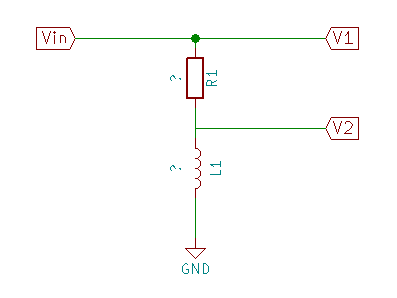 |
$V_{in}$ comes from a signal generator. I use Pure Data on my PC to generate a sine wave, then pipe the output from the sound card through an amplified speaker with a headphone jack. Sort of a signal generator on the cheap.
I measure $V_1$ and $V_2$ using my oscilloscope. It doesn’t matter if you measure peak to peak or RMS. It’s a sine wave. RMS and peak to peak are related by a simple ratio. Since it’s the ratio of $V_1$ to $V_2$ that I’m looking at, it doesn’t matter. Peak to peak is easiest, though, so that’s what I normally use. (Since it’s a ratio, it also doesn’t matter that my ‘scope is way out of calibration.)
First the math.
Formulated for the circuit given above: $V_2 = \frac{Z_{L1} * V_1}{Z_{R1} + Z_{L1}}$
Rearranged to find the impedance of the inductor: $Z_{L1} = \frac{Z_{R1}}{\frac{V_1}{V_2} - 1}$
Once you’ve got the impedance, you can find the inductance - provided you know the signal frequency.
This is how you calculate the impedance for an inductor at a given frequency: $Z_L = 2 * \pi * f* L$
Rearranged to find the inductance when given the impedance: $L = \frac {Z_L}{2 * \pi * f}$
Time to make some measurements and crunch some numbers. (I’ll spare you the screen shots of the oscilloscope, and save you a little bandwidth. You’ll just have to trust me on the measurements.)
| Parameter | Value |
|---|---|
| $R1 (ohms)$ | 200 |
| $f (herz)$ | 10k |
| $V_1 (V_{pp})$ | 6.85 |
| $V_2 (V_{pp})$ | 0.0663 |
| $Z_L (ohms)$ | 1.955 |
| $L1 (µH) $ | 31 |
That 31µH is a good ways away from the 49µH I was shooting for. Actually, I wanted 47µH but it was either 21 turns and 45µH or 22 turns and 48.8µH - at least according to the inductor calculator site I used.
That calculator seems to not account for spacing between the loops. That makes the inductance come out higher than you can actually reach with an insulated wire. If I were using lacquer insulated magnet wire, it’d probably be fine. The insulation on telephone wire is kind of thick, though, and that makes all the difference.
This calculator accounts for the spacing of the conductor turns. If I give it the same parameters as the first one, it comes back with 38µH.
Well, that’s closer to what I actually got. If I then measure the real length of the coil (27mm instead of the ideal 22mm) then I get 31µH - which is also the value I measured from the real coil.
According to that second calculator, I need 27 turns to reach 47µH - and that’s really 47µH. The calculated value is 47.13 µH for 27 turns of 1mm telephone wire (0.6mm plus insulation) on a 42mm core.
My hand made coil is about 20% off of the properly calculated value, and about 40% off of what I was aiming for - mostly because I didn’t understand what the online calculators were doing.
I’m not going to bother rewinding the coil, though. It works well enough as is.
“Art Attack” doesn’t demand precision. :)