Building an IV plotter from an Arduino Nano - Why am I doing this?
When I’m right, I’m right.
Building an IV plotter from an Arduino Nano - Table of Contents
The dispute behind this project started over a very simple circuit and a very simple task in a question on the Electrical Engineering Stack Exchange.
Here’s the circuit:
| Disputed circuit |
|---|
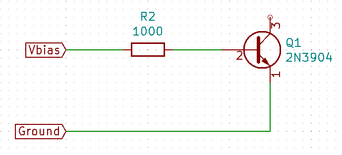 |
The question was actually a sort of homework question that a student posted. The student was assigned the task of setting up the given circuit, doing a voltage sweep on $V_{Bias}$, and plotting $V_{Bias}$ against the current through the transistor base. The student asked what the plot should look like, and what the circuit itself does.
The circuit itself is nothing but an example - a study object. The point of doing the lab work was to learn to setup the circuit and get familiar with the effects of voltage and current on the base junction of an NPN transistor. That is what I answered. I did not at that point intend to actually plot the thing.
Some time later, someone posted another answer which insisted that the question must have been incorrectly transcribed from the lab assignment to the EE Stack Exchange question.
That was obviously not the case because the question contained a picture of the assignment as the student received it. It definitely said to plot $V_{Bias}$ against the base current.
Worse, the other answer insisted that the question must be wrong because the resulting plot would be completely uninteresting - it would be nothing more than the IV curve of the resistor ($R_2$.)
That is wrong, but the person who posted it couldn’t be convinced otherwise with just words.
That’s the point at which I decided to plot the darned thing and see if a picture would be more convincing.
By that point a day or so had passed since the question was posted so I figured it would no longer help the questioner cheat if that had been the plan.
That was also conveniently late on a Saturday afternoon - yard work done and the evening free to push electrons.
I do not own an IV plotter. Many hobbyists have them. I don’t - or rather, didn’t.
Ordering one was out of the question - it would take several days to arrive, and by then there wouldn’t be any point in pursuing the dispute.
I built one out of bits and pieces I had at hand. That’s an Arduino Nano, a handful of passive components (resistors and capacitors) and a couple of banana jacks.
The result was this plot of the given task:
| Disputed IV plot |
|---|
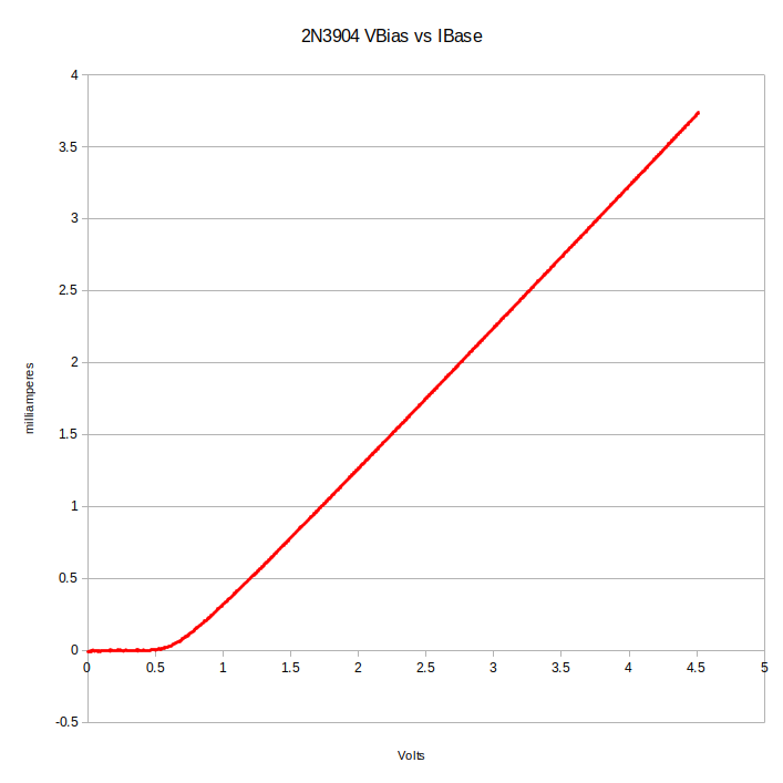 |
To my eyes, that is a very different thing than the simple straight line you would get from plotting current and voltage for a resistor.
Somehow, the other person saw this distinctly non-straight line as proof that the plot was nothing more than the IV plot of just the base resistor - you can’t win them all.
In another sense, I did win. I now have a functional (if somewhat limited) IV tracer and more posts to write.
The first version was a single port IV tracer. That’s all that was needed to accomplish the task. It could only handle single diode junctions.
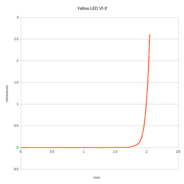
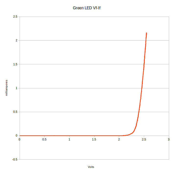
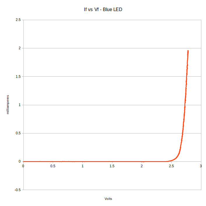
Besides the IV plot of the transistor base, it could do things like these LED forward voltage plots:
| LED IV plots |
|---|
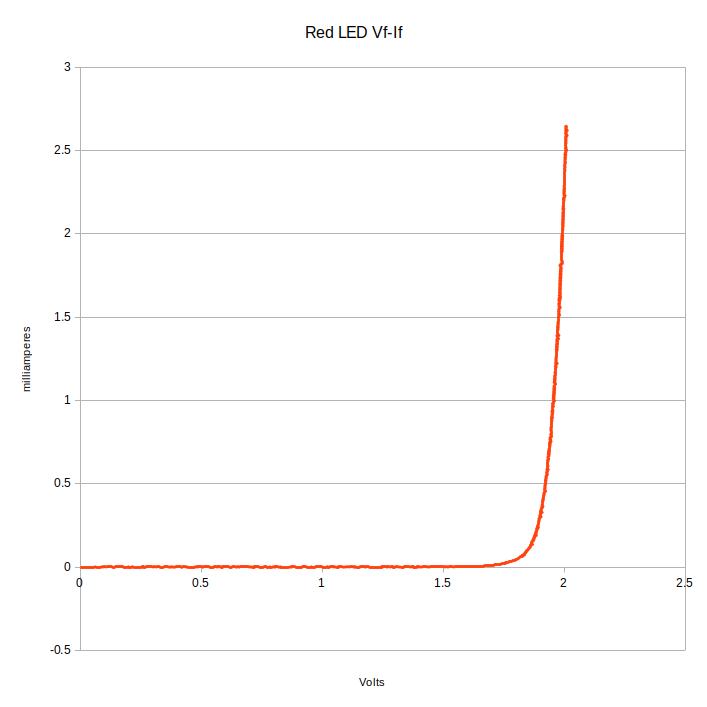 |
 |
 |
 |
The green LED plot is interesting to me.
Some time back, I built a gadget to light up a green LED from a 1.5V dry cell. In that post, I mentioned that it takes more than 2.2V to light up a green LED. The raw data says that there’s about 20 microamperes through the green LED at 2.2V. From there, the current rises dramatically.
The blue LED is something of a surprise. I’ve always read that blue LEDs needed 3V or more to light up. This one starts conducting at 2.5V, and is eye searingly bright before it gets to 3V.
After thinking about it a bit, I realized that a two port IV tracer only required one more resistor and one more analog input than the one port tracer. The Nano has plenty of ADCs and I’ve got plenty of resistors, so I extended the IV tracer to a full two port transistor tracer.
I can now make $I_B$ to $I_C$ traces of BJT transistors.
| $I_B$ to $I_C$ |
|---|
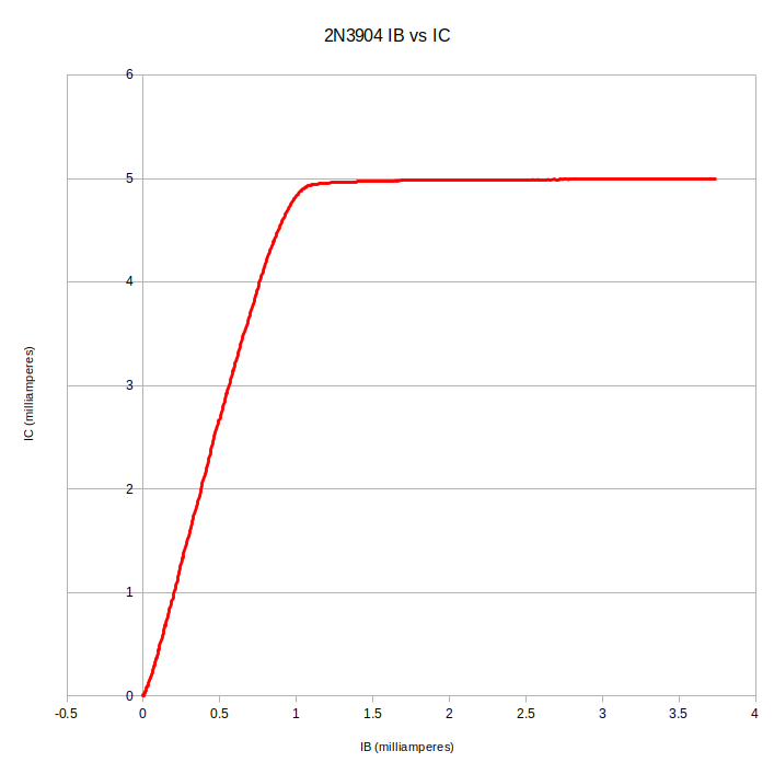 |
That’s a NPN 2N3904 transistor. I was going to do a plot of a 2N3906 PNP transistor, but I seem to have a problem. I don’t know yet what it is.
In the next few posts, I’ll explain how I generated a (somewhat) smooth, varying DC with the Nano, and how I calculated all the numbers. I’ll also be working on a better programm for the PC side. Right now I have a simple Python script that dumps the data to a CSV file. I made the plots from the CSV file with LibreOffice Calc. That gets old. I’m going to make a nifty GUI and use PyQTGraph to do the plotting - but not tonight.
At any rate, that’s the story behind how I ended up making an IV tracer one Saturday evening.
Building an IV plotter from an Arduino Nano - Table of Contents
Yes, I could have used LTspice or Qucs or some other simulator to make the plots. How much fun is that, though?