Building an IV plotter from an Arduino Nano - Designing a common emitter amplifier with Rodriguez - part 2
Lets take a “do over” on that biasing.
Building an IV plotter from an Arduino Nano - Table of Contents
I tried my hand at designing a biasing circuit for a common emitter amplifier using the IV curves of a 2N3904 transistor the other day.
I sat down today to build the circuit and see if reality and theory are anywhere close together - and discovered that I needed a reality check.
The values I calculated for the biasing resistors are wrong.
This is what I came up with the other day:
| Bad biasing |
|---|
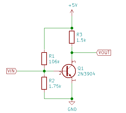 |
It looked odd when I did it. If you figure just R1 and R2 as a voltage divider, then you get about 0.074 volts at the base of Q1. That’s obviously not going to work.
It seems I got R2 wrong.
Looking things over, I think I dropped a zero while calculating R2 from the current and the base forward voltage. Using the same numbers (and doing the same calculation) today, I get 17.5k instead of 1.75k.
Corrected for the mistake, it should look like this:
| Better biasing |
|---|
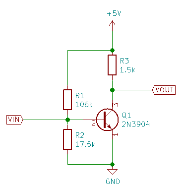 |
With that correction, the base voltage is reasonable, and the collector voltage comes out to 3.4V. Considering that I was shooting for 2.7V, that’s a pretty good bit off the mark.
The error has a lot of possible causes:
- The bias current (from the load line on the IV plot) could be wrong.
- The charts from Rodriguez are wrong.
- The biasing resistors are wrong because I made (another) mistake in the calculations.
- The resistor values are off (I had to use various combinations of series and parallel resistors to get the required values.) The values are within 10% of the calculated resistances, though, which is all you could ask for in olden day when people designed circuits by the load line/IV chart method.
- Something else that I haven’t thought of.
After some experimenting, I find that I need a bias current of about 3.4 to 3.5 microamperes (Rodriguez has about 10 nanoamperes of noise when measuring microamperes) to get the collector voltage that I was aiming for. That makes the value I got from the load line wrong.
Further experiments show that my bias circuit is probably delivering about 1.2 microamperes to the base of the transistor. That makes my bias resistor calculation wrong, as well.
Drat.
I get to start all over.
I’m going to have to find a better description of the process of picking the bias current from a load line on an IV plot. I don’t see an obvious error in the drawings I made - just eyeballing the IV chart with the load line gives me a value of about 4 microamperes.
The math for the biasing resistors is also wrong - damifino where.
I’m going to leave this sitting for a few days while I try to get a grip on the process.
I did the experiments to find the source of the errors using a quickly hacked Python script to drive the Rodriguez Arduino hardware. It generates specific output voltages and delivers the corresponding base current (measured using the same methods as Rodriguez uses.) I measured the collector voltage with my multimeter.
That’s one advantage of making your own gadgets - you know how they work so you can modify them for other tasks.
The down side of making your own gadgets is that you’re never sure if the gadget is working right. I don’t quite trust Rodriguez, so I end up having to do experiments to find possible error sources.
If you’re interested in the hacked Python script, I’ve posted it here. It isn’t useful enough in general to get its own github repository.
Building an IV plotter from an Arduino Nano - Table of Contents