Building an IV plotter from an Arduino Nano - Designing a common emitter amplifier with Rodriguez - part 3
Revising Rodriguez’s base current measurements.
Building an IV plotter from an Arduino Nano - Table of Contents
The last time I tried to work on the 2N3904 amplifier, I found that I’d gotten the required base current wrong.
I sat down today and worked on figuring out how I got the wrong value.
It turns out there were a couple of things going on that caused it.
First was that the base current display was rounding to the next microampere. That’s bad because at the base current needed for this transistor, a difference of 0.5 microamperes is rather drastic.
The second thing going on was that measuring fractions of microamperes is just a tad beyond the hardware I was using with Rodriguez. Specifically, the resistor for the base current measurments was a bit too small.
I changed the base current display from milliamperes to microamperes, and rounded it to 0.01 microamperes.
Then, I changed the hardware to use a 3.3k resistor instead of the original 1k.
The base current measurments are more consistent from run to run, now. They are also more evenly spaced.
The new IV trace for the 2N3904 transistor I’ve been playing with looks like this:
| New 2N3904 IV plot |
|---|
 |
It doesn’t look all that different from the one I started with, but the values in the base current display changed a good bit in some places:
| Old 2N3904 IV plot |
|---|
 |
I drew load lines on the new IV plot, and… didn’t get what I expected.
| New load line |
|---|
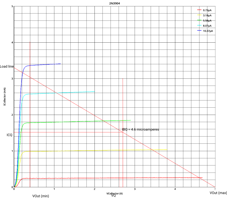 |
I expected to get something closer to 3.5 microamperes (as I measured it the last time I worked on this.) Instead, I got more. That’s 4.6 microamperes instead of the 4.1 microamperes from the original IV plot.
Now what?
It turns out that 4.1 to 4.6 microamperes is correct.
I double checked everything, and found that the collector resistor wasn’t 1.5k as I used in the calculations and for the load line. It was 1.75k. That made all the difference. A base current of 4.4 microamperes puts the collector voltage at 2.7V exactly.
I didn’t have a 1.5k resistor, so I had assembled a few resistors in a series and parallel combination that (by calculation) should have been 1.5k, but wasn’t. I measured it, found it too high, then added another resistor in parallel to get it down to 1.5k.
All happy. The load line method to determine the base current works.
I’ll go back over the calculations for the bias network another time. I know they are wrong, I just don’t know where I messed up.
It looks like I’m going to have to put an entry field in the Rodriguez GUI for the reference voltage for the ADC. It is supposed to be 5.0V, but it turns out that my Nano has 4.75V.
Another day.
Building an IV plotter from an Arduino Nano - Table of Contents