Building an IV plotter from an Arduino Nano - Designing a common emitter amplifier with Rodriguez - part 4
Three time’s a charm.
Building an IV plotter from an Arduino Nano - Table of Contents
My third attempt at designing a common emitter amplifier with Rodriguez seems to have succeeded.
I had to revamp Rodriguez a little, and I looked up a different explanation of how to calculate the resistors for the voltage divider for the base biasing.
For Rodriguez, I added the ability to change the base resistor to get better results with very low currents. I also added an input field for the ADC reference voltage, and for the collector resistor.
The net result is that the results are more precise at the low bias currents needed for a modern small signal amplifier transistor.
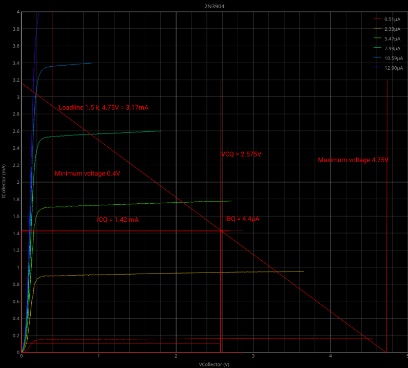
Here’s the IV-trace for my 2N3904 transistor with the load line and other information already drawn on it:
| 2N3904 load line design |
|---|
 |
You may notice I gave Rodriguez the ability to produce plots with a black background again. The white background is better for printing, but the black background is easier to work with on the computer screen. Rodriguez has a button to switch between black and white backgrounds.
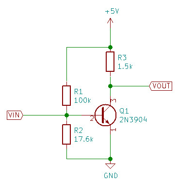
This is the final circuit as designed from the load line:
| Simple 2N3904 common emitter amplifier |
|---|
 |
Here’s the data I started from:
- $V_{cc}$ = 4.75 volts - that’s the supply voltage of the Arduino Nano that I’ve tapped to provide power to the amplifier.
- $R_{Collector}$ = 1.5k - chosen to be large than the collector resistor from Rodriguez to keep all values within the measured ranges.
- $I_{Collector maximum}$ = 3.167mA - calculated as $I_{Collector maximum} = \frac{V_{cc}}{R_{Collector}}$
- $V_{Collector quiescent}$ = 2.575V - picked from the IV chart. I wanted to keep the transistor out of saturation, so I picked 0.4V as the lower limit and 4.75V as the upper limit. The middle is 2.575V - that’s what should be on the collector when there’s no signal on the input.
- $V_{base}$ = 0.65V. That’s a typical value you’ll find as an approximation all over the internet. In my case, it is the actual measured base voltage of my transistor at room temperature.
From those values, I plotted the load line on the transistor IV chart and calculated the values for the bias resistors.
From the IV chart, I found the $I_{base quiescent}$ to be approximately 4.4 microamperes.
From the above linked source, I calculated the values of R1 and R2:
- $I_{R1} = 10 \times I_{base quiescent} $ = 44 microamperes
- $R1 = \frac {V_{cc}-V_{base}}{I_{R1}} $ = 100k
- $R2 = \frac {V_{base}}{I_{R1}-I_{base quiescent}} $ = 17.6k
Those are the values in the schematic above.
The resistors must match the requirements exactly. A 99k resistor is bad. I combined resistors in series and parallel combinations until I got resistors for R1 and R2 closer than 100 ohms each to the design values.
With the circuit assembled, I get a measured $V_{Collector quiescent}$ of 2.6V - that’s pretty darned close to the design value.
The finished circuit does amplify. With an input of 25mV peak to peak at 1kHz, I get an output signal of 2V peak to peak. That’s a gain of 80.
The gain wasn’t designed, it’s just what the circuit delivers. Designing a specific gain would have required an emitter resistor.
I’ll spare you a photo of the completed circuit - it’s a spider web mess of tacked together components. It is only intended to prove the concept, not to be a working tool.
From all of that, I conclude that Rodriguez is a useable tool for designing small amplifiers by the load line method.
Here are the limitations of Rodriguez that will affect your circuit design:
- Driving voltage - you’ve only got about 5V to play with. That’s the voltage limit for the power supply of your amplifier.
- Collector current - with 5V and the standard 1k resistor, you are limited to 5mA of collector current. You can’t really reduce the collector resistor without causing problems, so you are stuck with really low output current in your design.
- Base current - transistors with really high $\beta$ require really low base currents to go with the low collector current that Rodriguez can produce. The $\beta$ of about 350 that my transistor has is about the limit. The base current measurements are already somewhat flaky. I used a 200k resistor in series with the base connection to get the base current down. Better measurements of the base current would require a larger base resistor on the Rodriguez hardware, but that would introduce inaccuracies from the impedance of the ADC input in comparison to the resistor. 3.3k is about as high as I want to go given that the ADCs of the Nano have an input impedance that is often quoted as around 10k.
Conclusion:
- Rodriguez will do for small, low current, low voltage amplifiers like the (pretend) microphone amplifier I used as a design example. You won’t be designing any high power class A speaker amplifiers with it - and if you are designing that kind of thing then I’d hope you’ve got better tools than an Arduino and some scrapings from the bottom of the junk drawer.
- Rodriguez is useful for hobbyists interested in trying their hand at amplifier design using components available almost everywhere.
- Rodriguez demonstrates how to make use of oversampling to get better results out of a low resolution ADC.
Building an IV plotter from an Arduino Nano - Table of Contents
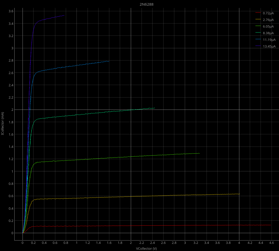
For fun, I ran an IV plot of a 2N6288 power transistor I had laying around.
I got a bit of a surprise. The datasheet gives an $h_{fe}$ of a minimum of 20 for this part. I’m getting something like 200 out of it.
That kind of makes me wonder how well it would work as a small signal amplifier.
| 2N6288 |
|---|
 |