Building an IV plotter from an Arduino Nano - Taking a look at a tunnel diode
Surprise time.
Building an IV plotter from an Arduino Nano - Table of Contents
Somebody on the Electrical Engineering Stackexchange recently mentioned tunnel diodes in connection with current and voltage plots, and that of course gave me ideas.
I ordered a few GI103A tunnel diodes from Amazon. Amazon thinks the diodes will be delivered next week some time, but they got here today. A friendly fellow in Russia stuffed 4 GI103A diodes in a padded envelope and sent them my way posthaste. Thank you, Maxim Chayko.
The GI103A is a germanium tunnel diode made in Russia. I picked a low current model since I know Rodriguez isn’t up to anything big. The GI103A is rated for 1.3mA peak current.
Here’s the current/voltage plot from the GI103A datasheet:
| GI103A original |
|---|
 |
I kind of wanted to duplicate that trace.
It turns out that Rodriguez can’t do it.
Rodriguez can’t plot the negative resistance range. There’s a point at which the resistance goes negative, and the next point after that it is positive again. That whole negative resistance curve takes place in one single step of the PWM output.
That kind of sucks, because I can’t reproduce the negative resistance plot.
On the othe hand, it makes picking the bias voltage for a tunnel diode oscillator an absolute breeze.
Here’s Rodriguez’s take on the IV plot of the GI103A:
| GI103A by Rodriguez |
|---|
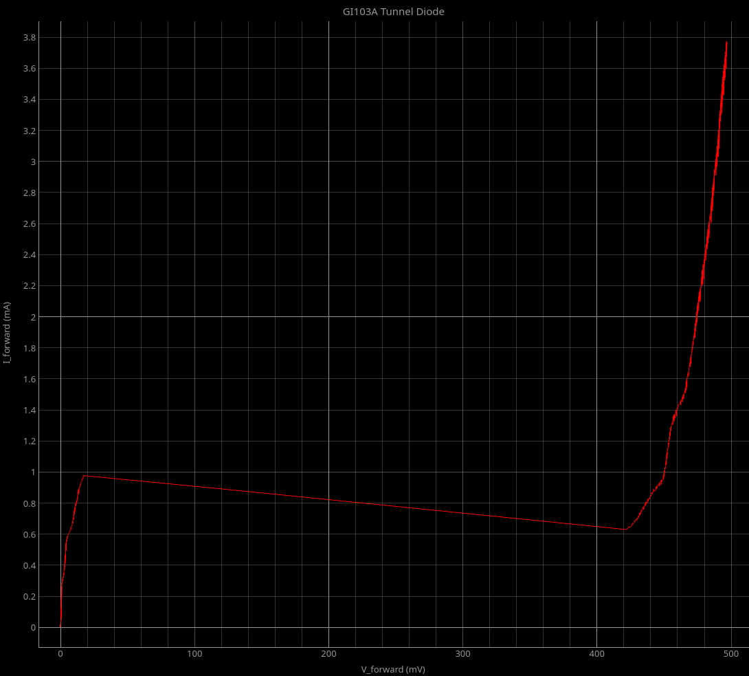 |
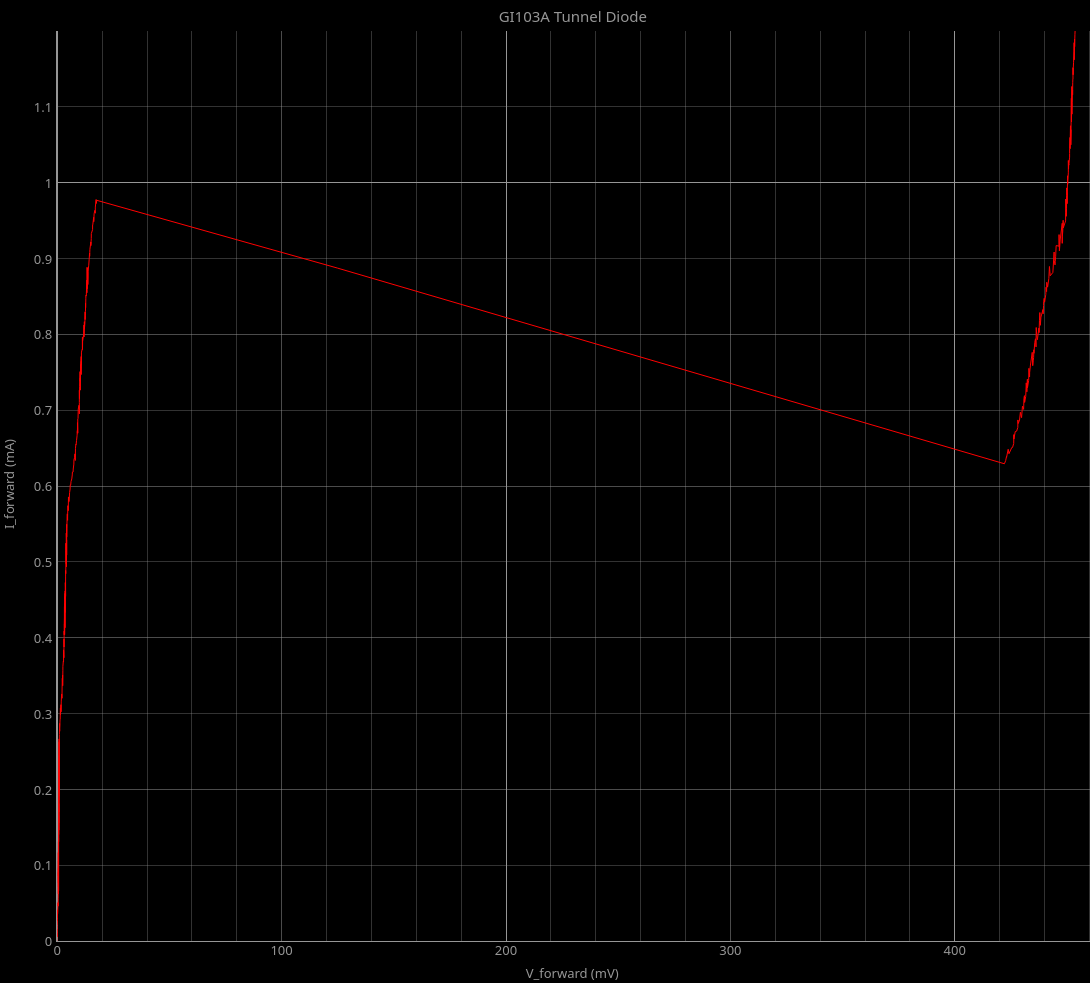 |
The whole negative resistance range is that straight line between 0.019V and 0.422V.
You can’t see the details of the negative resistance section, but if you calculate the midpoint of the voltage at each end of the straight section then you get the ideal bias voltage for a tunnel diode oscillator made with that diode.
As a matter of fact, you can get pretty much everything you need to set up the biasing right off of the Rodriguez display. You just use the mouse and the readouts to get the voltage and current at each end, then do a little math.
Here’s an IV plot of my GI103A marked up with the values from Rodriguez:
| Designing a GI103A oscillator |
|---|
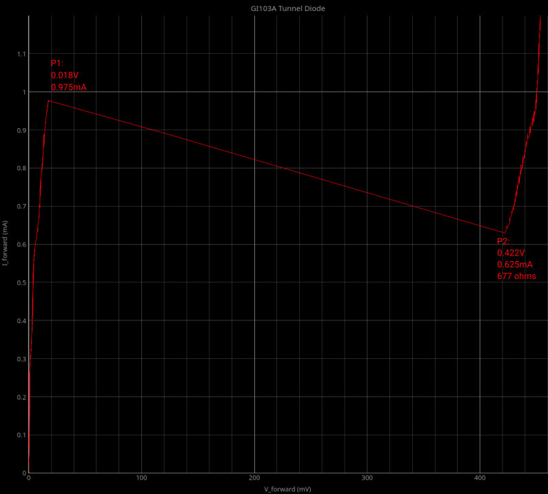 |
Here’s a simple oscillator circuit made with the GI103A:
| Tunnel diode oscillator |
|---|
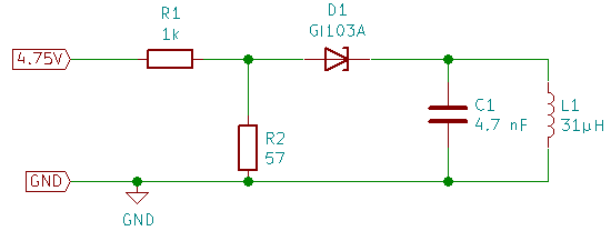 |
The bias voltage is simple: \(V_ {bias} = \frac {V_{P1} + V_{P2}}{2}\)
That puts the bias dead center in the negative resistance range.
The next step is to make a voltage divider to generate the bias voltage.
For that, you need to pick your supply voltage and one resistor.
I’m using $V_{supply} = 4.75V$ because that’s what I’ve got handy.
I picked a 1k resistor because I have a bunch of them scattered around my workbench from working with Rodriguez. I’ll call that $R_A$.
Now all I need is a second resistor called $R_B$.
From the voltage divider equations, I can find $R_B$ from $R_A$, the supply voltage, and the output voltage:
\[R_B = R_A \times \frac {1}{\frac{V_{supply}}{V_{bias}} -1}\]That gets me 48.5 ohms for $R_B$.
I can use $R_A$ as R1 in my oscillator. If I use $R_B$ for R2 in the oscillator circuit, it won’t work well.
I marked a resistance at P2 in the plot up there. That resistance messes with the biasing. It effectively makes R2 smaller than it should be - the bias voltage will be low.
You need to figure out a resistor for R2 that gives you the calculated $R_B$ when combined with $R_{P2}$
You get R2 from $R_B$ like this:
\[R2 = \frac{1}{\frac{1}{R_B}-\frac{1}{R_{P2}}}\]That works out to about 53 ohms.
I’m using 57 ohms for R2 because that’s what I could easily combine. I had a 47 ohm resistor handy, and that’s a tad too small - the output level drops noticeably if I switch from 57 to 47. The bias voltage is also too low at 0.179V when using the 47 ohm resistor. At 57 ohms, the bias is off just a tiny bit at 0.217V.
If I cobble more resistors together to get 53 ohms, then I get a little more output level and the bias voltage goes up to 0.220V where it belongs.
Here’s the output of the oscillator using the values above:
| Tunnel diode oscillator output |
|---|
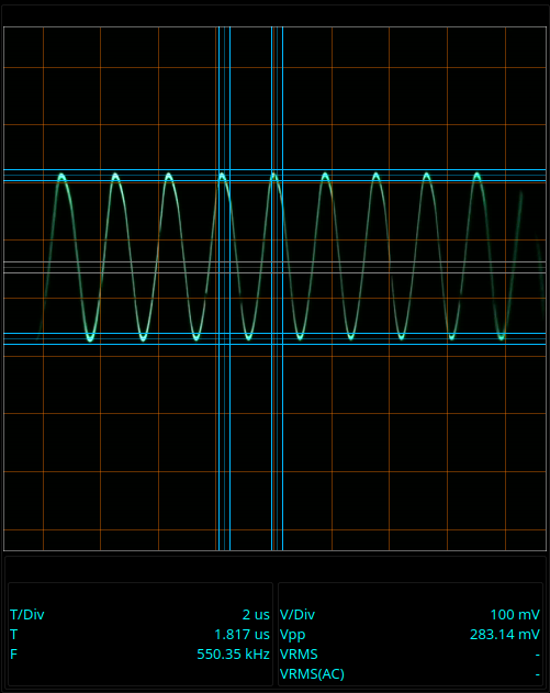 |
Note the signal level - 280mV peak to peak is no great shakes. That’s the downside of tunnel diode oscillators. They are low power devices. That’s low current and low voltage.
On the other hand, they are pretty danged simple to design. Figure the biasing, add a resonant tank (simple inductor/capacitor parallel circuit,) done.
The frequency should have been 417kHz, but it is off by a good bit.
Part of that is due to my (ancient, analog) scope not having been calibrated in ages. Part of it is no doubt due to the hand wound coil I’m using. It could easily be off a good bit at high frequencies. I calculated 417kHz for the combination of 4.7nF and 31µH. Add uncalibrated scope to hand made, imprecise coil and, yeah, I’ll buy “off by 30% to hit 550kHz instead.”
Anyway, that was a fun evening that I wasn’t expecting. Now it’s time to put away my toys and get some shuteye.
Building an IV plotter from an Arduino Nano - Table of Contents