Building an IV plotter from an Arduino Nano - Measuring current with an Arduino
Ohm’s law doesn’t require a current shunt.
Building an IV plotter from an Arduino Nano - Table of Contents
An Arduino Nano has eight analog to digital converters (ADCs) for measuring voltages, but nothing explicitly for measuring current.
That’s not necessary, of course.
A voltmeter and a known resistance is all it takes to measure current.
Any transistor circuit will include resistors to limit the current through the device. Since the resistances are known, all you need to measure are the voltages. Apply a little math via Ohm’s law to the known resistances and the measured voltages and you get the current.
Ohm’s law says the product of current and resistance gives voltage.
\[E = I \times R\]Where:
- $E$ is the voltage in volts
- $I$ is the current in amperes
- $R$ is the resistance in ohms
The Wikipedia page uses V for voltage. I learned Ohm’s law so long ago that they still used E (for “electromotive force.”) We did measure it in volts back then, we just used the symbol E in the equations.
You may notice that Ohm’s law as stated tells you the voltage given current and resistance. Well, it’s “just math.” If you survived high school algebra then you know how to rearrange such a simple equation to isolate any desired variable.
We want current from voltage and resistance, so we can restate Ohm’s law this way:
\[I = \frac {E}{R}\]The circuit of the original, simple version of the IV tracer looked like this:
| Single junction IV tracer circuit |
|---|
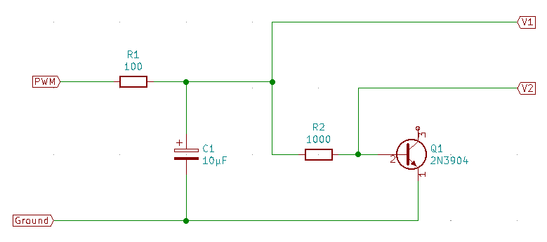 |
What I needed was the voltage at V1 (the bias voltage) and the current through the base of the transistor.
R2 is in series with the base of Q1, so the current through R2 and the current through the base of Q1 must be the same.
The voltage across R2 is just the difference of V1 and V2, so the current through the base can be calculated by the following equation:
\[I_{Base} = I_{R2} = \frac {V1-V2} {R2}\]If I extend the circuit to measure all needed voltages and currents for a two junction IV tracer, the circuit looks like this:
| Two junction IV tracer circuit |
|---|
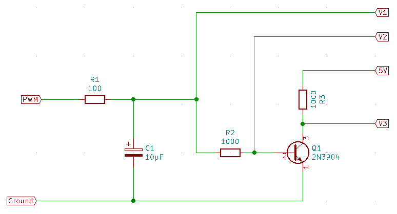 |
The 5V point isn’t measured. The Arduino uses the 5V supply as the reference for the ADC. Measuring the 5V would always return 5V because they are by definition the same.
The additional circuitry leads to this equation for the collector current of Q1:
\[I_{C} = I_{R3} = \frac{5-V3}{R3}\]The Arduino program in fact measures only V1, V2, and V3 and sends them to the PC. The PC program has the resistor values and does all the calculations.
The values I used for the resistors were indirectly dictated by the pulse width modulation frequency I use to generate the bias voltage.
I used 100 ohms for R1 because the Arduino outputs can’t deliver large currents. At 5V, and assuming a completely discharged C1, the PWM output will only have to deliver a maximum of 50mA. That’s strictly above the specified limits of the ATMega 328P, but the pulses are very short when C1 is empty so the total energy is low enough not to do any damage.
I chose C1 by eyeball (large, but not too large) then checked that the cutoff frequency formed by it and R1 was far lower than the 10kHz PWM signal. The 159Hz cutoff frequency is just short of 6 octaves below the 10kHz PWM signal. The filter approximately halves the pulse height for every octave, so it has a so-so attentuation of the PWM frequency of about 18 dB. It attenuates the 10kHz pulses to about 1/10 their original height.
From R1 follows R2. R2 must be much larger than R1, or else the bias voltage will not get up close to the 5V maximum. I chose R2 to be 1000 ohms - that’s ten times R1. That keeps the load on R1 low enough that the bias voltage gets up to around 4.5V at the maximum duty cycle.
R3 is simply a duplicate of R2 for no better reason than that I had the 1k resistors in hand and couldn’t think of a particular reason why the collector resistor might need to be a different value.
So, there you have it. How to measure current with an Arduino Nano, and why I chose the component values I used in the IV tracer.
Yes, the business about Ohm’s law is old hat to anyone who has studied electronics.
I figure, though, that anyone building a copy of this IV tracer will be a beginner looking for an easy to build circuit. I included the background because I think it’s a disservice to not explain things to beginners. “Build this. Whee! It works! Why?” My explanation may not be the best, but at least it has key words that can be used to find better descriptions.
Building an IV plotter from an Arduino Nano - Table of Contents