Building an IV plotter from an Arduino Nano - Now that I've got it, how do I use it?
Designing a common emitter amplifier with Rodriguez.
Building an IV plotter from an Arduino Nano - Table of Contents
Now that Rodriguez is (more or less) complete, I figure it is time to see if it is useful.
Due to the hardware limitations I set myself when I started (nothing more than what I had available on a Saturday evening,) Rodriguez has a limited voltage and current range for the charts it produces. Lacking experience in transistor amplifier design, I have no idea if those limits are wide enough for Rodriguez to be a useful tool or whether Rodriguez is only suitable as a learning excercise.
As it happens, I have need of a small amplifier.
My wife and I occasionally make video conference calls with our kids. Both kids live a couple of hours drive away, so visits are a bit scarce - especially with the travel restrictions due to the covid pandemic.
We have a laptop attached to the (big) TV in the living room. There’s a webcam perched on top of the TV. Sound comes from the HDMI cable to the TV, and I have a microphone that we set out close to the couch.
When it works right, it’s like sitting together with the kids in the living room and having a chat.
Unfortunately, the microphone isn’t all that whoopy.
Discord does it’s best to eliminate echoes and clean up the noisy microphone signal, but I really need something better.
I actually do have a better microphone. I own a Radio Shack pressure zone microphone (PZM, also called a boundary microphone) that I bought over 25 years ago. I was doing some experiments back then in recording in noisy environments, and wanted to see if the PZM principle would help (I don’t think it did.) I’ve long since lost the little amplifier/power box that was part of the microphone when it was new.
I need an amplifier for my PZM to use with Discord. The output level of the capsule is very low - too low to use with a laptop microphone input.
I bodged together a small amplifier a few days ago using a circuit from the internet. It uses a 2N3904, and has a gain of about 100 (call it 20dB.) I have no idea how it was originally designed. Its output level is adequate for use with a laptop.
I’m going to design my own 2N3904 based amplifier using an IV trace from Rodriguez. I want to get a gain of 100 out of it, and I want it to operate on 5V.
I found a decent explanation of the process on a page from Analog Devices. The linked page describes the design of a common emitter amplifier using a voltage divider to bias the transistor.
The IV trace is apparently used to determine the required base current for a given collector resistor. The IV trace is also used to determine the collector current for the given collector resistor and base current.
Here’s the trace of the 2N3904 transistor I’ll be using:
| 2N3904 IV Curve |
|---|
 |
This is a basic sketch of a common emitter (CE) transistor amplifier:
| CE amplifier |
|---|
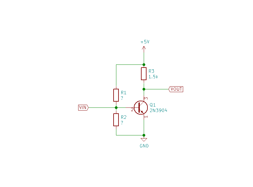 |
I’ve chosen R3 (that’s the collector resistor) as 1.5k. Here we’ve already hit a limitation of Rodriguez. Rodriguez uses a 1k resistor and the 5V Arduino power supply to generate the collector current while doing the trace. The highest collector current Rodriguez can possibly plot is 5 milliamperes - and generally less for various reasons. I can’t reasonably change that 1k, so anything I design with Rodriguez will have a maximum collector current of 5 milliamperes - I have to stay within the bounds of the trace data.
With R3 at 1.5k, I have a maximum collector current of 3.3 milliamperes. That’s 5V divided by 1.5k.
With the maximum collector current and the supply voltage, I can draw a load line on the IV trace, and from that I can find the base current needed to properly bias the transistor.
| Load line |
|---|
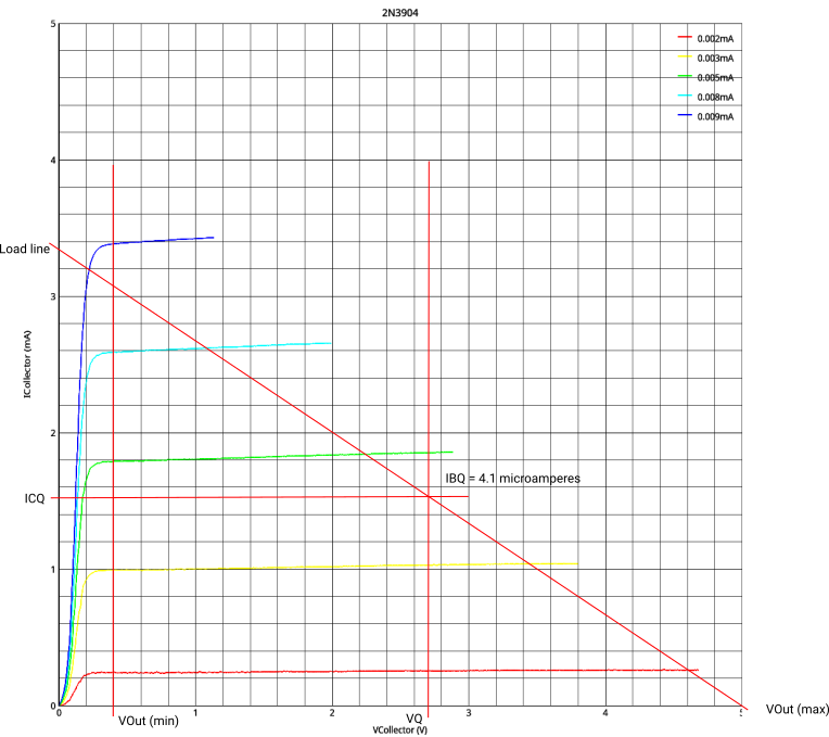 |
I’ve drawn more lines on there than I expected I’d need to.
There’s the load line, of course. Then I want to keep the output out of saturation, so I drew a (vertical) line at the lowest output voltage (that’s 0.4V.) Half between that lowest output voltage and the maximum (5V,) I drew a vertical line (that’s at 2.7V.) The intersection of the vertical line and the load line is the bias current. I measured that in reference to the next higher base current from the IV traces - that’s the 5 microampere line. It works out to 4.1 microamperes of base current to put the output voltage in the middle of the range I want (0.4 to 5.0V.)
From the base current, I can now calculate R1 and R2.
Edit 2021-01-24:
The value for R2 is wrong. It should be 17.5k instead of 1.75k. I dropped a zero somewhere while doing the calculations.
Summarising the description from the Analog Devices page:
- Set $I_{R2} = 9 \times I_{base} = 9 \times 4.1 microamperes = 36.9 microamperes$
- The maximum value for $ R_{max} = \frac {V_{supply} - V_{BE}}{I_{base}} = \frac {5V-0.65V}{4.1microamperes} = 1.06 Mohm$
- The current through $I_{R1} = 10 \times I_{base} = 41 microamperes$
- $ R1 = \frac {R1_{max}}{10} = 106kohm $
- $R2 = \frac{V_{BE}}{I_{R2}} = \frac {0.65V}{36.9 microamperes} = 1.75 kohm$
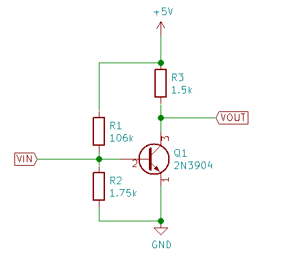
OK. There we have it. R1 = 106k, R2 = 1.75k.
The common emitter amplifier ought to look like this:
| CE amplifier |
|---|
 |
There’s lots more to do, but I’m going to leave it at that for tonight.
I’ll put the circuit together when I get some time, and see if the output voltage lands where I wanted it.
Another time. It’s time to get some shuteye now.
Building an IV plotter from an Arduino Nano - Table of Contents