The Telefunken Jubilate 1161 tube radio - Cleanup and renovation
Some things you’ve just got to replace.
Click here to see all the Telefunken Jubilate 1161 posts.
It has taken much longer to get the Jubilate finished than I planned on. Not that there was anything really difficult or complicated about, it is just that I was on vacation for a while. Shortly after I got back from that trip, I managed to break my right leg and couldn’t climb up to the attic where my workbench is.
I suppose it worked out for the best, though, since now my wife and I can give the radio back to her brother as a Christmas present. Not so much the radio, as the work and the replacement parts.
First off was cleaning it up. I didn’t make any pictures of that. It was mostly just carefully vacuuming out the dust by brushing the insides with a soft bristle brush and vacuuming the dust out of the air.
The only real trick to cleaning such old radios is that you have to be careful around the tuning coils:
| Caution: fine wires |
|---|
 |
 |
Some of the coils have hair fine wires connecting them to the chassis. If you break one of those, it can be a real pain to diagnose and repair the problem.
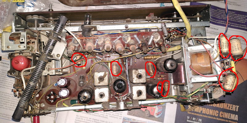
As you can see in that picture, I’ve already cleaned out the dust bunnies. I’ve also replaced the old selenium bridge rectifier with modern silicon diodes and replaced the large electrolytic capacitor for the 250VDC supply with a pair of new electrolytics. The new capacitors are much smaller but still have the correct voltage rating and capacitance value.
| Upgraded power supply |
|---|
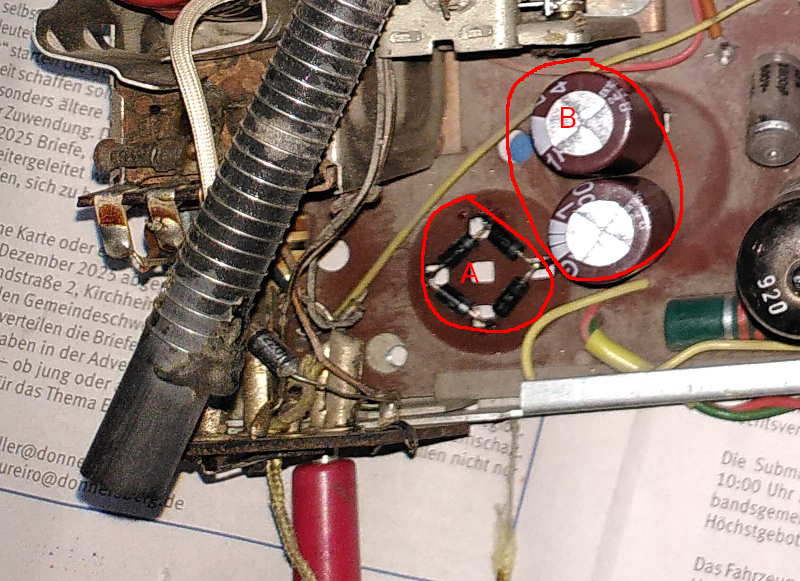 |
“A” is a diode bridge made of four 1N4007 diodes. They are good for 1A of current and 1000V, making them very well suited for this use. “B” marks the two 47µF electrolytic capacitors, each rated for 400VDC. The maximum voltage here is 250VDC. I prefer to use overrated parts for the electrolytics - it gives them a longer lifetime. There was originally one capacitor there with three pins and two capacitors inside. I don’t know where you can get something like that, and I didn’t try. I just replaced them with good, modern parts.
One other thing you really need to do with old tube equipment is to replace the paper and wax capacitors. They get warm, what with the tubes all around them, and the wax ages and runs out. That lowers the capacitance, and raises the electrical leakage - besides not having the capacity at AC that they need, the begin to act as resistors at DC. The leakage can pull the bias voltages out of whack between stages or on voltage dividers that set the bias voltage. That kind of thing can lead to the tubes not operating properly and running harder than needed - they go bad or burn out. Even if that weren’t the case, since the paper and wax capacitors are often used to couple amplifier stages, the lowered capacitance alone can result in loss of volume.
| Paper and wax capacitors |
|---|
 |
 |
 |
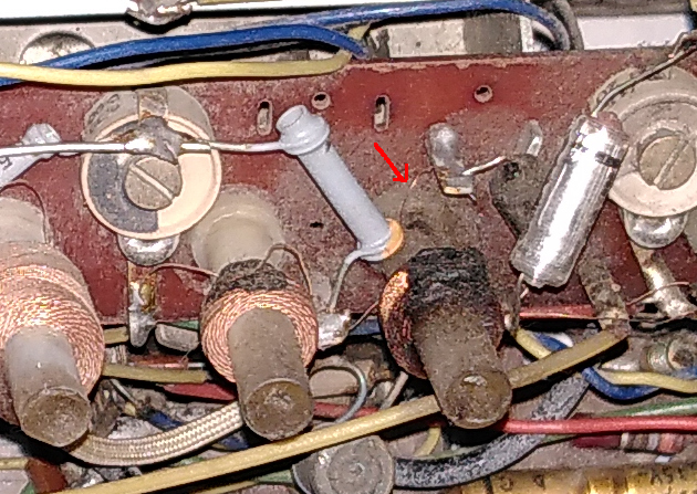
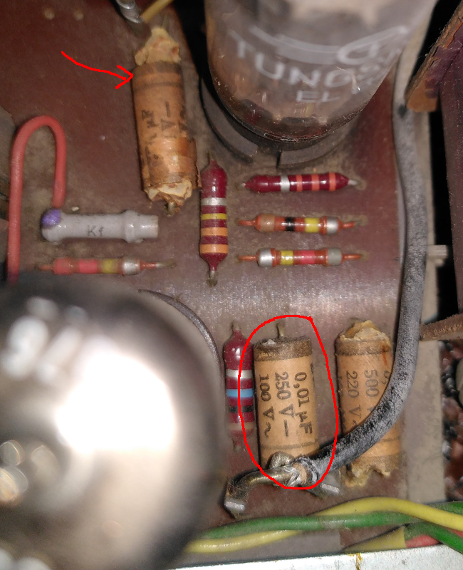
The capacitor with the red arrow has melted and the wax has run out. The circled capacitor is a strange part that I could not properly replace. That capacitor has a grounded shield layer. There were three pins - two for the capacitor to be used as a coupling capacitor between two stages, and a third pin connected to a layer of conductive foil wrapped around the capacitor itself. That grounded shield was to prevent interference from other signals. I’ve never seen a modern capacitor like that, so I simply replaced it with a normal foil capacitor with the proper capacitance and voltage rating. It seems to work well enough - nothing hums or whistles or has any outside interference on any band.
I used foil capacitors to replace all of the paper and wax ones. I left the others (except for the electrolytics) as they were.
The foil capacitors I used were rated for 400 or 1000VDC. Lower rated parts weren’t any cheaper, so they might as well have more safety margin - and, besides that, the higher rated parts are a bit bigger letting them match the original mounting holes better.
All in all, I replaced ten parts:
| Replaced parts |
|---|
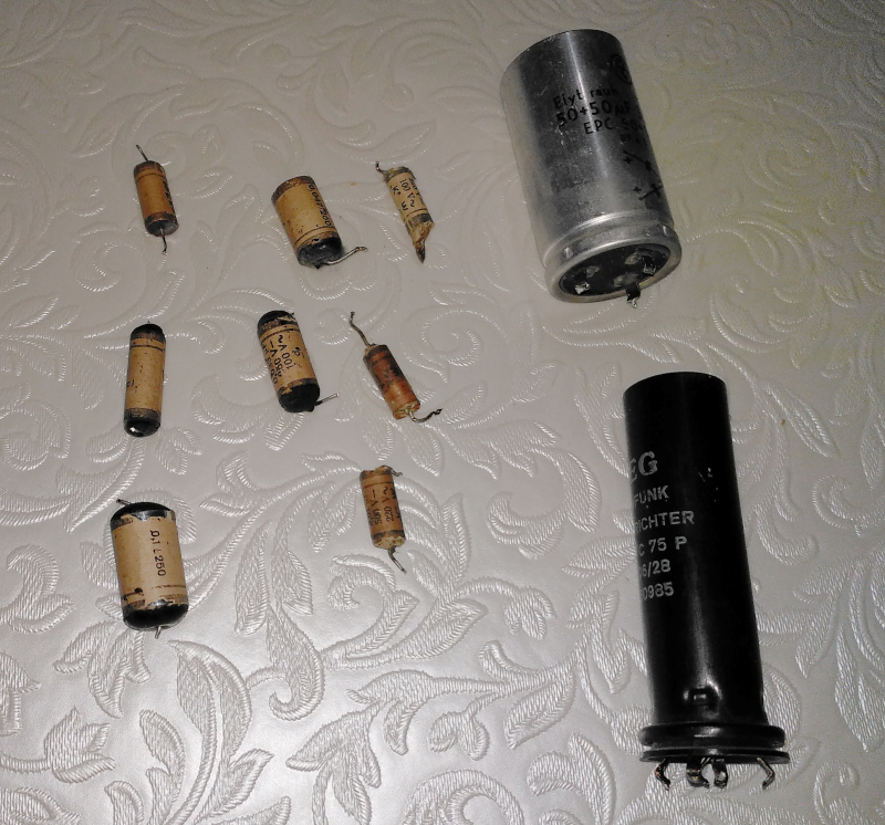 |
That’s eight paper and wax capacitors, a double electrolytic capacitor, and the selenium diode bridge.
The selenium diode bridges make me nervous - they like to go “poof” and stink up the house. When you replace one with a silicon diode bridge, you need to make sure that the voltage doesn’t go up. The selenium bridges often have a very high forward voltage (tens of volts.) You want to stay close to the designed voltage. In this case, the DC power is 250VDC. After replacing the selenium bridge with the 1N4007 bridge, the DC voltage was 253VDC. Close enough. When I did the same thing with a Blaupunkt Granada, the DC voltage jumped from 250 to 300VDC. I used some Zener diodes on that one to lower it to 250VDC. That wasn’t needed here.
There were then a few mechanical details to fix up.
The knobs were all stiff - a couple of drops of sewing machine oil did wonders, except for on the tone control. It was completely stuck. Somebody seems to have put paint or threadlock in it. I got it moving again, but it is very stiff.
The knobs were straight up filthy, and they were missing the decorative discs in the center of the smaller knobs. By the time I got all the grunge out and off of the knobs, the gold painted trim was pretty well gone. I used a small can of gold flake paint like you use on plastic models to fix the trim on the knobs. I also painted the centers of the small knobs metal flake gold. Nobody is going to mistake it for original, but it beats the heck out of filthy and glue spotted.
That’s about it for the repair and cleanup. Next time around I’ll show you how I modernised the Jubilate to be a Bluetooth speaker.