The Sunday afternoon junkbox LED driver
Whiling away a rainy Sunday afternoon with a block of salt and an LED.
The salt block lamp - Table of Contents
| Block of rocksalt and a GU4 3 watt LED |
|---|
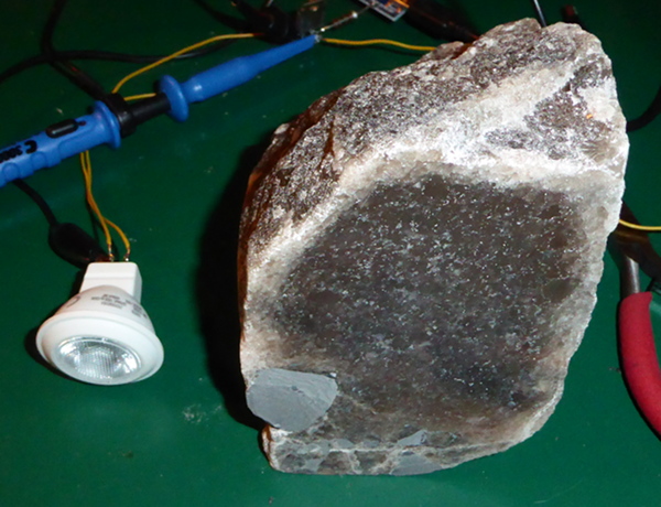 |
While on vacation a couple of months ago, I bought a block of rock salt at the Berchtesgaden Salzbergwerk in Berchtesgaden, Germany.
The salt there isn’t your typical pure table salt, and it isn’t the typical “himalayan pink” salt that you can buy as candle holders from Amazon or Ikea. It has a lot of iron oxide in it, so it’s more of a red/brown color. I bought a block of really dark salt - seriously impure, with a rock of some kind embedded in it. It looks more interesting than the purer, cleaner, stuff. Most of the salt there is mined with a hot water pump system, and it’s purified before being sold - the table salt they make out of it doesn’t taste like rust like my block does. They do mine some small amounts (like the block I bought) to make things out of - I could have bought a genuine Berchtesgaden rock salt candle holder or electric lamp at the shop at the mine. They cost about 30 Euros or more (my salt block was “only” 13Euros.) You can buy cheaper ones from the souvenir shops in town, but those don’t use real Berchtesgadener salt - the souvenir shops all sell what looks like the same thing you can buy from Ikea or Amazon - but at twice the price.
I’ve already started working on the block itself. I flattened two sides (bottom and front,) and polished the front side. You can see it in that picture up there.
The plan is to mount it in a wooden stand with a back light, and to carve some kind of doohicky in the front side. A bunny rabbit, or a rose. Maybe a titmouse (well, why not?) I haven’t decided yet. It sort of depends on what it looks like when it’s lit up.
I bought a 3 watt LED at the hardware store the other day, and decided that the crummy weather today was a good excuse to hide away in my work room and see what my salt block looks like.
The LED says it is made to operate from 12 volts, and that it is not dimmable. I take that to mean that it can’t be dimmed with the dimmable transformers like you can get for 12 volt halogen lights. This thing is made to replace 12V halogen bulbs, so I figured I need to give it 12V. It does say it’ll take AC or DC, so that’s a plus. It also says it’s rated for 370 milliamperes.
I’ve mentioned before that my work room is kind of bare bones. Anything I can get by without, I ain’t got.
I don’t own an adjustable power supply. I’ve got wall warts of all kinds, some that will even put out 12 volts. They don’t have a current limited output, though.
I thought it over, and whilst thinking, I saw the coil I made for the simple voltage booster. On a whim, I replaced the green LED from the simple voltage booster with my 3 watt LED, and ran the wire across the file. It took a little practice, but I could get that high power LED to light up brightly from a 1.5 volt alkaline cell.
OK, that’s the solution.
I rummaged around a bit and found a 2N6288 NPN transistor (7 amperes $I_C$, 30 volts $V_{CEO}$) on an old scrap PCB. Rooted another Arduino Nano out of my stash of knock offs, and it’s off to the races.
The basic idea is to use the Nano to drive the coil as a voltage booster. With a bit of software, I can control the switching frequency and duty cycle.
The booster part is simple enough:
| Nano controlled voltage booster |
|---|
 |
| Pulsesignal is a PWM output from the Nano. |
| +1.5V is from a D size alkaline cell. |
A little experimentation showed that it worked best with about a 26kHz switching rate. I can then vary the duty cycle between 22 percent (just barely on) to 88 percent (full brightness.) Of course, “full brightness” isn’t a bright as it’d be when driven from a regular power supply. It’s still bright enough to get an impression of what it will look like.
| Dim LED |
|---|
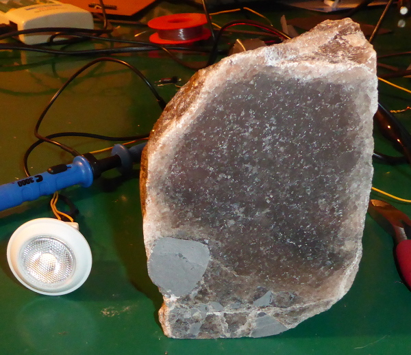 |
| That’s at 22% duty cycle. Below that it won’t light up at all. |
| Bright LED |
|---|
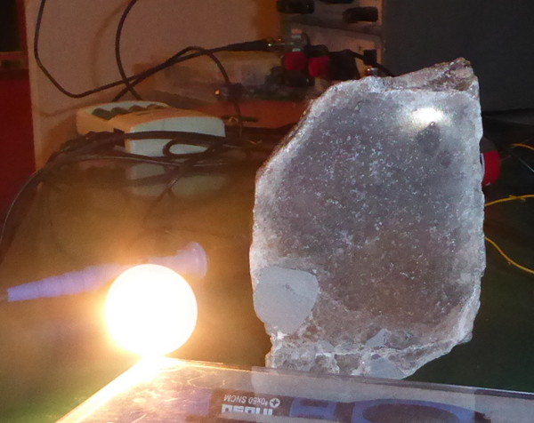 |
| That’s at 88% duty cycle. Above 88% it gets dimmer again. |
| Lighted block |
|---|
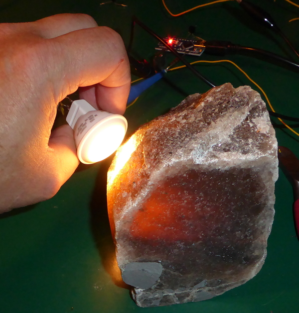 |
It lights up the block pretty well. I think if I run the same circuit from a 5 volt power supply it’ll be bright enough so that I can use the duty cycle to regulate it to the correct brightness.
In case anyone is interested, here’s what the drive to the LED looks like:
| Dim drive |
|---|
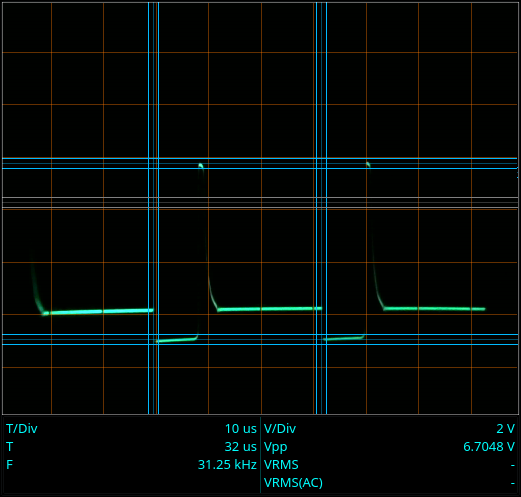 |
| The high peak is when the LED is lit. The lowest voltage is during the charge cycle (22%, so about 8 microseconds.) The intermediate voltage is when the transistor is open, but the coil is discharged. |
| Bright drive |
|---|
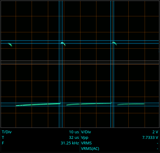 |
| The charge time has been extended to cover all of the cycle time except for the discharge. The discharge time more than doubles, and the voltage goes up higher and stays higher over the whole discharge period. Once the charge time starts eating into the discharge time (higher duty cycle,) the LED gets dimmer. |
It seems there’s some sort of regulation going on inside the LED. It lights at around 6.7 volts. If it didn’t have some kind of regulation built in, then the 12 volts it is rated for would destroy it. I guess I could have just connected it to 12 volts and gotten on with it, but where’s the fun in that?
That’s all for today. There’s a long way to go before my rock salt lamp is finished, but it won’t be getting done on this Sunday.