A sewing machine motor speed control - Basic ideas on how not to make a motor speed control
Simple but not really useful.
A sewing machine motor speed control - Table of Contents
I’m going to start this series with a look at the simplest, most naive motor control there is.
The simplest conceptual motor speed controller is a variable resistor in series between the motor and the power supply. More resistance means less current means the motor turns slower.
Such a controller would look like this:
| Simple, naive motor control |
|---|
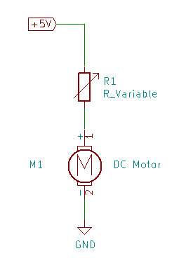 |
Nothing to it. A power supply, a variable resistor, a motor.
That’s all a typical sewing machine controller is.
| Sewing machine motor with control |
|---|
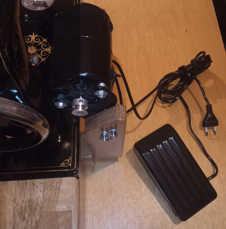 |
You’ve got a power supply (the mains plug,) a motor (screwed to the wooden upright,) and a (somewhat) variable resistor hiding in the foot pedal.
The foot pedal actually contains some big resistors and some switches arranged so that pressing down on the pedal successivelly shorts more resistors to allow more current to reach the motor. Since it uses just a few resistors you don’t have really fine control - you’ve got maybe five resistance values.
There’s several downsides to the controllers used on sewing machines, and only one upside.
The one advantage is that the controller is simple. Not so much a big deal in this day and age, but back in the days when sewing machines were first electrified there wasn’t really any good way to control motor speed. Electronics meant vacuum tubes, which were expensive and sensitive to vibration. No way was anybody going to put any kind of complicated circuitry in something that was going to be literally kicked around.
There are several downsides:
- Such controllers are wasteful.
- Such controllers have only a few distinct control steps.
- They don’t maintain a specific speed.
A resistor always converts current to heat. To slow down the motor, you put more resistance in series with it. The power the motor doesn’t use is wasted as heat.
The few available control steps don’t allow for fine control of the motor speed. You step on the pedal, and the motor turns. It speeds up, goes too fast, and then you back off to slow down - and now it’s too slow, so step on it again and it’s too fast.
Worst of all is that the speed control isn’t a speed control. It is actually a power control. It works like the accelerator in a car - mashing down on the pedal feeds more power to the motor. The speed the motor turns at is determined by the power and the load. For the same power, the motor turns faster when it has a light load than when it has a heavy load.
For a sewing machine, that last means that the machine slows down when you cross a thicker seam and speeds up when you get back to a lighter section.
In electronics terms, a sewing machine motor control is open loop. It changes its output according to the control input (the pedal,) but it doesn’t monitor the motor to see if it matches the desired speed.
I put together a simple circuit to illustrate the load control problem. It uses an IRF540 N-channel MOSFET to control the speed of a small motor.
| Test circuit |
|---|
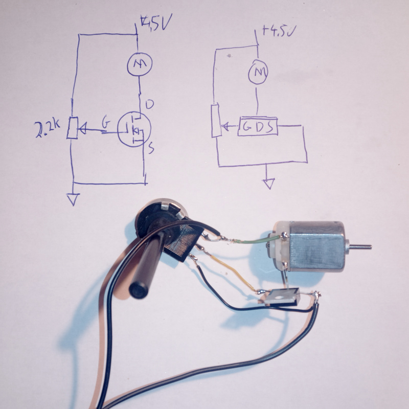 |
I don’t have a rheostat (variable resistor) that could handle the motor power requirements without burning out, so I made that circuit to do the same job.
The potentiometer controls the gate voltage on the MOSFET. Higher voltage on the gate means more current through the drain - the MOSFET acts like a voltage controlled resistor. Turning the potentiometer varies the gate voltage, making the motor run faster or slower. The MOSFET can handle a fairly large amount of power - at least in comparison with what my dinky little motor draws.
You can see how putting a load on the motor makes it slow down and how removing the load (letting go of the shaft) lets the motor speed up.
Sewing machines do the same thing when using the typical simple foot pedal controls.
I’ll take a look at a (slightly) improved version of this controller the next time around.