A sewing machine motor speed control - Mounting brackets
Sawing, drilling, sanding and tapping.
A sewing machine motor speed control - Table of Contents
I got some time to work on the motor control for my Adler class 8 sewing machine again today. The controller has to be mounted somewhere close to the motor. Since I don’t want to modify the machine or make changes to the box the machine sits on, the controller will have to be mounted on the motor itself. That was today’s project - four brass mounting straps to hold the controller on the motor.
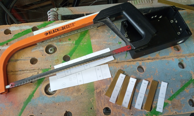
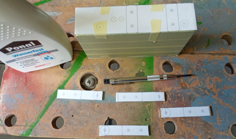
As usual, I started by making some measurements and drawings. The results were a set of templates to mark the mounting holes and the shape of the mounting straps. I’ll put all the templates together with the PCB files and program code when the whole thing is done. I’m not keeping things secret, I just want to make sure I’ve got it all together and (more or less) right before I put it where someone might try to duplicate it.
I made the straps fromm a piece of 2mmx15mmx1000mm brass strap that I had bought for something else then never used. That seems to happen a lot. I get an idea, buy (or scrounge) stuff to do it, then get a better idea that is simpler and then have stuff left over that I didn’t use.
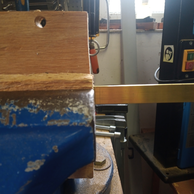
I’m going to start this off with a trick that drives my father in law crazy - free hand cutting straight lines.
| Cutting brass strips |
|---|
 |
 |
 |
 |
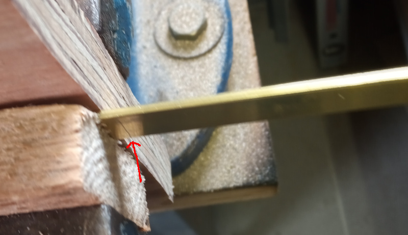
The vise is mounted so that the jaws are parallel to the floor - most vises are. That makes the vertical edges really vertical. I put the piece I’m cutting in the vise so that the edges line up and so that the line I’m cutting goes straight down. The wood scraps holding the brass are also lined up to be parallel to the cut. Having all the edges lined up makes it easier to see that I’m cutting straight, and having the cut vertical makes it easier to follow the line - the saw “wants” to go straight down. Get all the stuff lined up, then get yourself positioned so that your arm goes in a straight line while working the saw. Easy.
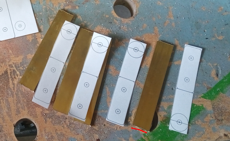
The cuts didn’t have to be perfect here. The pieces only needed to be sort of the right size so that the templates fit.
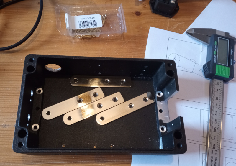
I had intended to make mounting brackets that attached to the bottom of the control box, so I drilled and tapped those holes last week. I changed my mind because I couldn’t convince myself that I could make the needed bent brackets - I’ve bent brass before, but the parts got all scratched. I want this to look somewhat nice, so I changed to simple straight brackets.
I can’t fill the holes and I’m not going to start over with the box, so there’ll be some unused holes in the bottom of it that nobody will ever see. Maybe they’ll let in some air. Right.
| “Ventilation” holes |
|---|
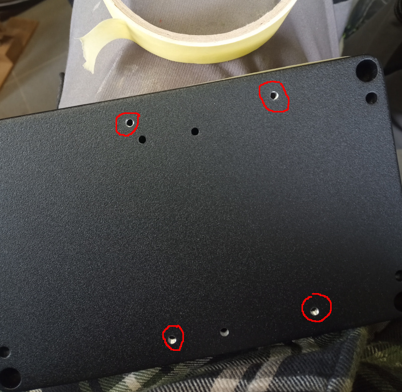 |
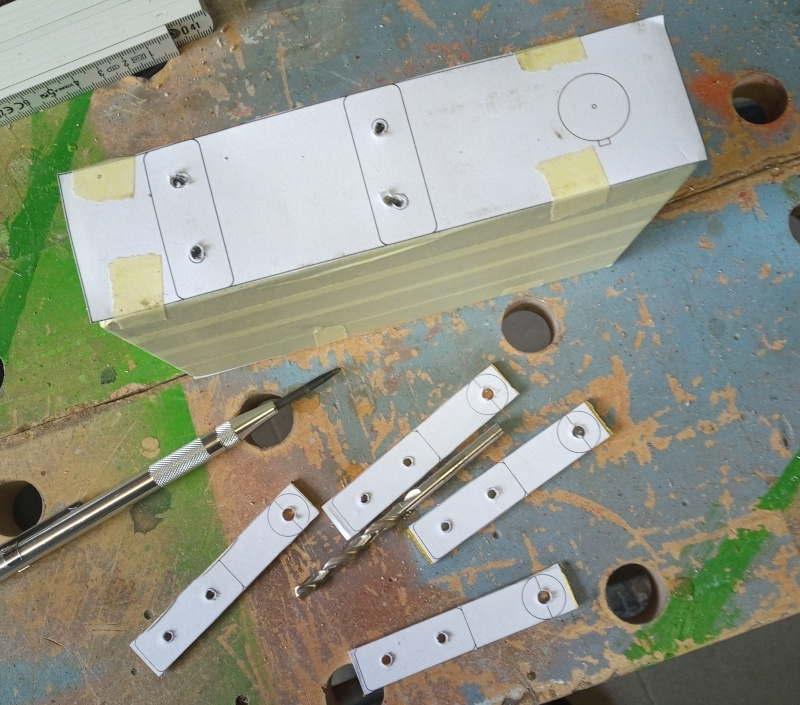
Using straight mounting brackets meant I had to put holes in the sides of the box. I extended the templates I used last week, then taped up the box and put the new templates on. I used white glue to put the templates on the brass brackets.
| Ready to drill |
|---|
 |
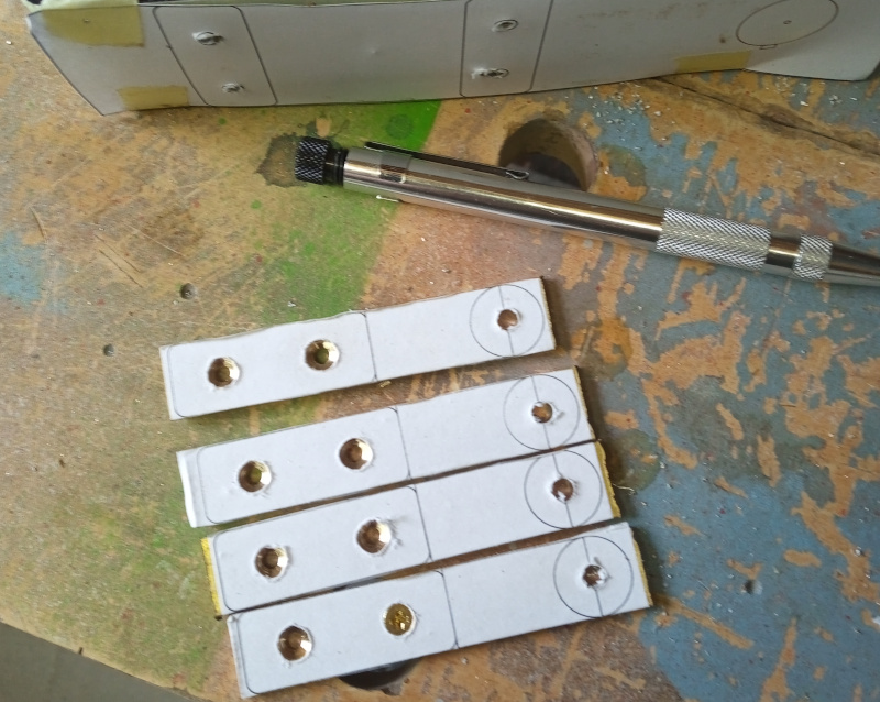
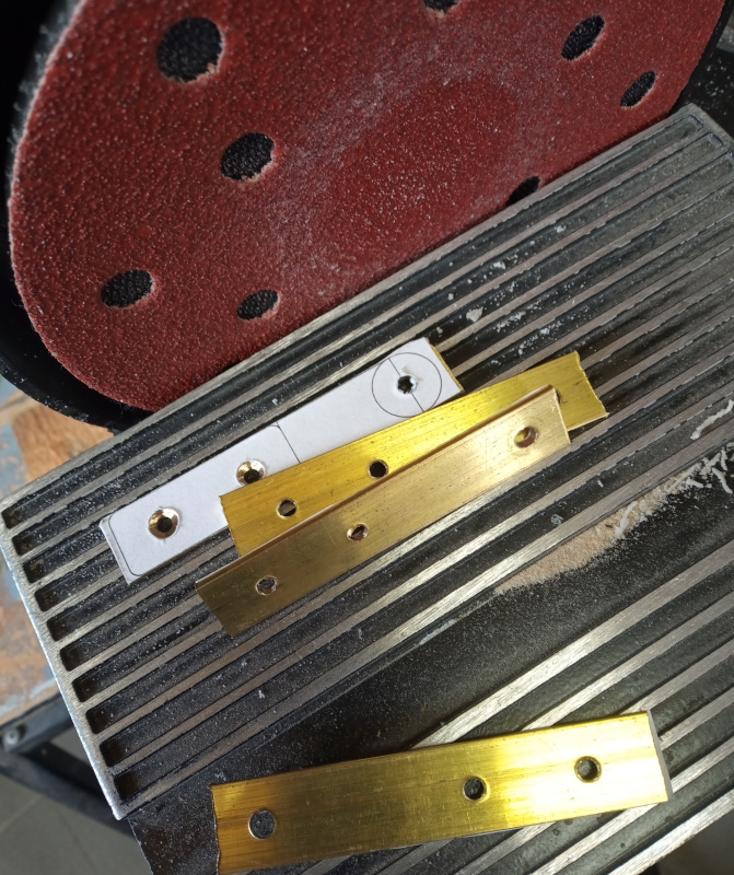
I drilled the holes with my old drill press, then used a larger drill bit to countersink the holes in the brackets.
| Drilled and countersunk |
|---|
 |
 |
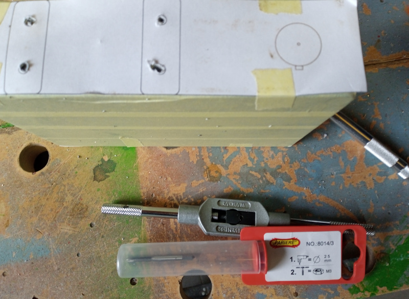
The new holes in the box were drilled to 2.5mm then tapped for M3 screws.
| Tapping holes |
|---|
 |
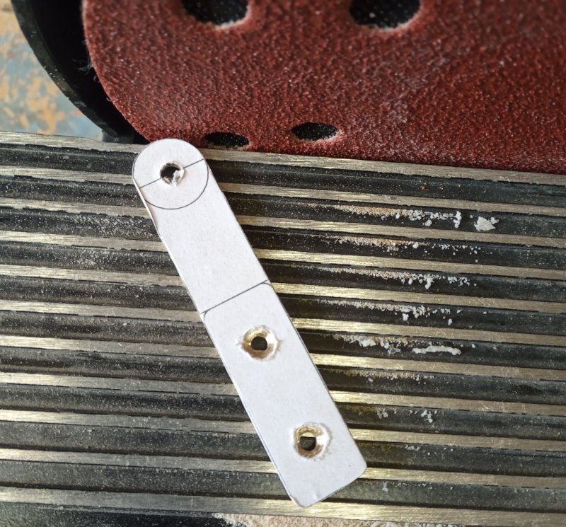
The reason it didn’t matter if the brackets were cut exactly straight is because I used the disk sander to grind the brackets to their final shape. They had some rough edges on the back that I knocked off with the belt sander.
| Sand to shape |
|---|
 |
 |
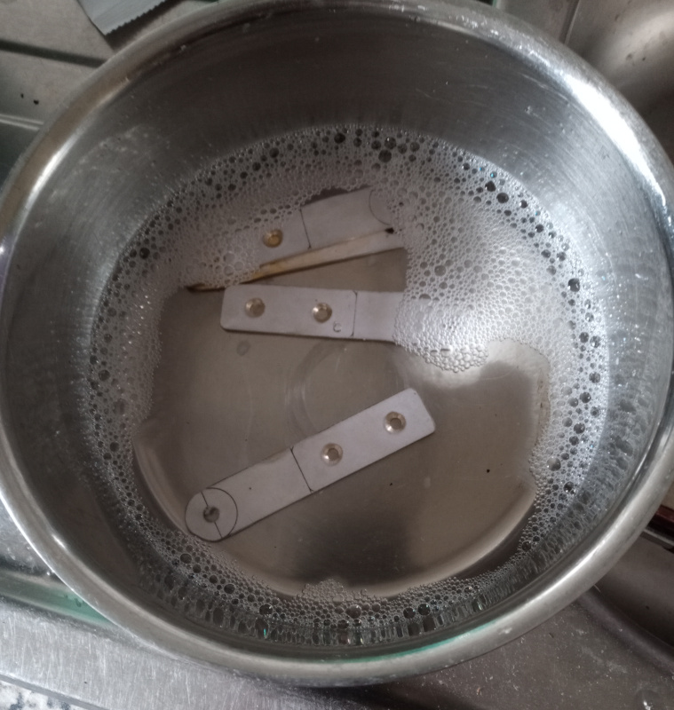
With all the metal working done, it was time to remove the templates. A soak in warm soapy water dissolved the paper and washed off the rest of the glue.
| Clean up |
|---|
 |
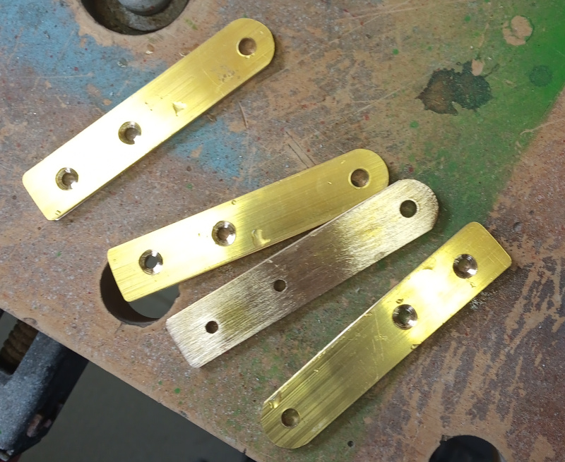 |
The clean brackets looked a little dull - it was time to polish them up.
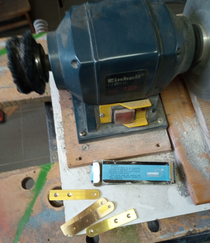
| Polishing brass |
|---|
 |
 |
I use a cloth wheel in a bench grinder to polish metal. The polishing compound usually leaves streaks of oily stuff all over things, so I washed them in solvent after polishing them.
I think the parts look pretty good.
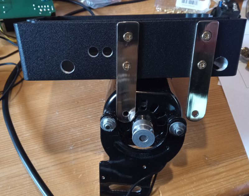
I have to modify the motor because the screws aren’t long enough. That means completely disassembling the motor and putting it back together using threaded rod sections that are about one centimeter longer than the originals. I’ll do that next weekend.
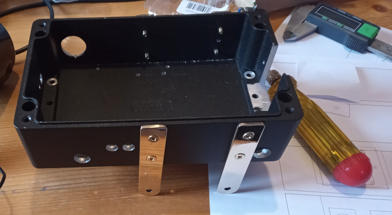
Here’s what the box looks like with the brackets on it.
| Finished brackets |
|---|
 |
 |
Not very impressive for an entire afternoon’s work, is it? That’s how it goes, though. None of it is difficult, it just takes a while to do it. If you watch YouTube videos or read project descriptions, you’ll often come away with the impression that things are quick and easy. Most of the time they aren’t really hard, but they are time consuming.
There’s still the mounting for the tachometer pickup and the foot pedal to build - then software to write.