A sewing machine motor speed control - A look at the insides of the finished control
A lurid crawl through Bigfoot’s entrails.
A sewing machine motor speed control - Table of Contents
I’ve updated the Bigfoot repository to include some details of the tachometer and to fix some of the missing bits in the schematic.
To do that, I had to take the controller apart to see what I had done to get things to run properly. I made some photos while I had it open.
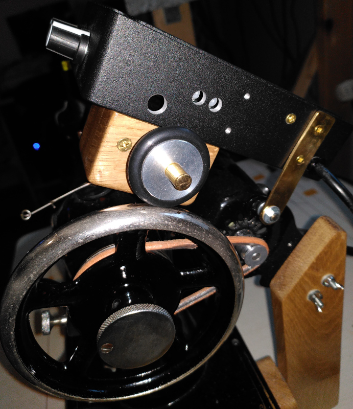
To start with, a look around the controller’s outsides:
| Bigfoot from the outside |
|---|
 |
 |
 |
 |
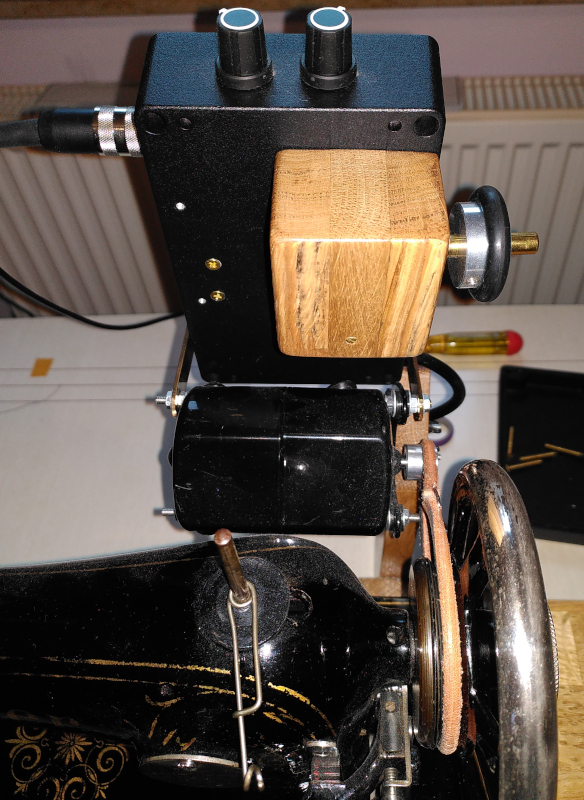
Those mostly just show how the control box and the tachometer are mounted on the motor. You can also see how the tachometer picks up the handwheel rotations.
If you look closely, you’ll see that there are far more holes in the box than are strictly needed. My plans for mounting the box changed a couple of times, as did the plans for mounting the tachometer. By the time it was all done with, things went together with fewer screws than I had thought would be needed. I didn’t want to start over with a new box, so I’ll just have to live with the extra “ventilation.”
The tachometer is mounted inside the wooden box beneath the controller. There’s a small PCB in there, along with an FL-08 bearing. The slotted wheel is screwed to the end of the brass rod. Do you know what’s tricky? Drilling a hole down the center of an 8mm rod with a wobbly drill press and a handmarked center point.
| Tachometer |
|---|
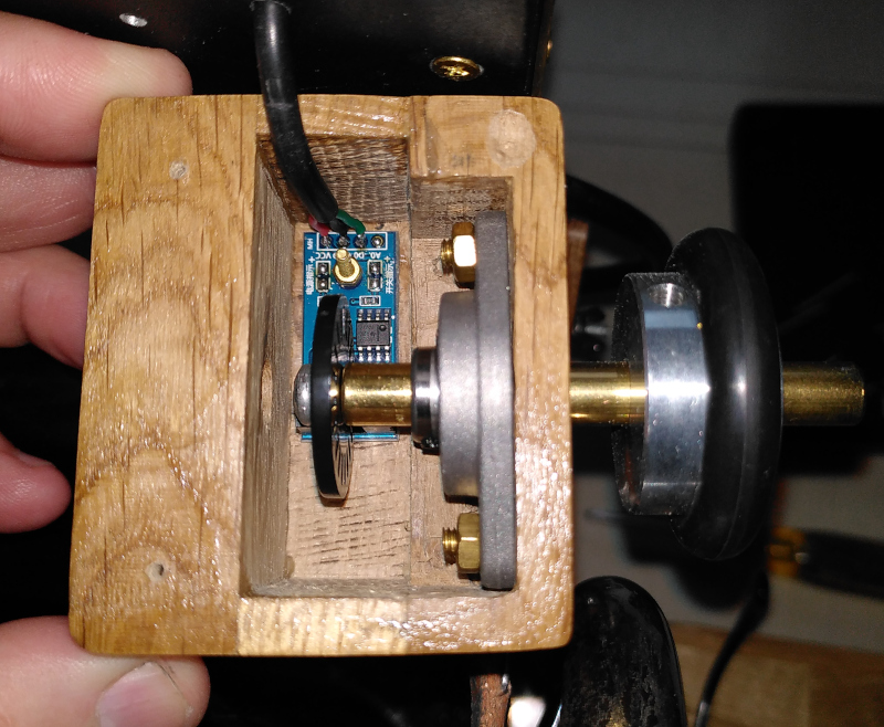 |
The wooden housing was cut from three scraps of 19mm thick oak board. I cut them to shape on the bandsaw, then used a wood chisel to cut the pocket for the bearing after I glued the pieces together.
The wiring for the tachometer goes through a hole in the bottom of the metal box of the controller.
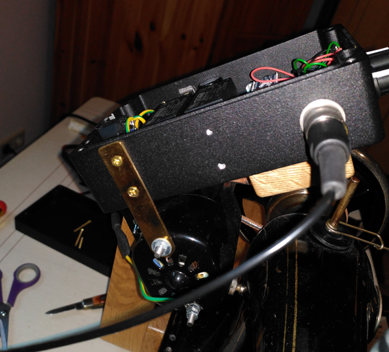
I take safety seriously. One of the first questions I was asked on the Hackaday.io Bigfoot project page was whether or not I installed a fuse in Bigfoot.
Yes, I did. It is part of the C14 socket I installed for the power cord. Bigfoot is also properly grounded - that’s the metal controller box and the motor itself.
| Fuse |
|---|
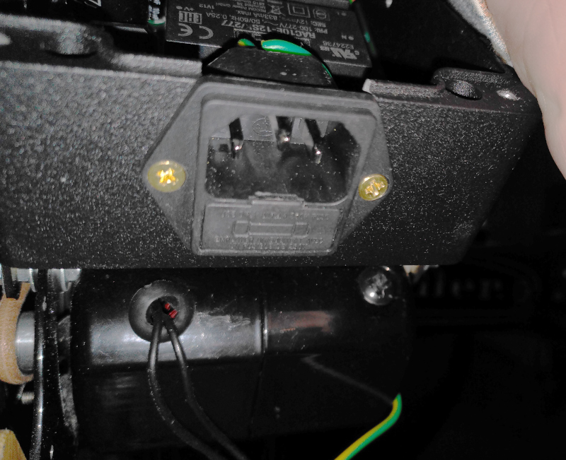 |
There’s a green and yellow ground wire running from the controller to the motor there along the bottom of the picture.
Finally, we get to the promised gizzards and guts of the Bigfoot.
| Bigfoot internals |
|---|
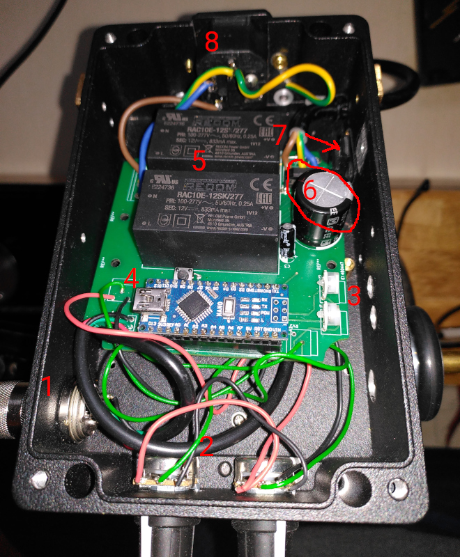 |
There’s quite a few things of interest in that picture:
- Socket for the pedal cable. I used a plug and socket with screw on threads - once it’s plugged in, it ain’t comin’ out. I also put a fairly long cable on the pedal - it drives me nuts to have the cable just barely reach where I need the pedal to be (or worse, just not quite reach where I want it to be.)
- Front potentiometers. Those two control the available speed range. The left one is the low speed setting. The fixed speed range on the pedal uses that speed. Once you get above the fixed speed position on the pedal, the speed varies linearly between the low speed and the maximum speed set with the right potentiometer.
- Internal potentiometers. The one furthest back sets the “stop” position for the foot pedal. The other one sets the position for the transition to the linear speed control. When the pedal position lies between those two values, the motor runs at a fixed speed.
- Arduino Nano. The brains of the outfit. It reads the potentiometers and the foot pedal, then decides how much power to feed to the motor to maintain the speed as reported by the tachometer.
- Two isolated 230VAC to 12VDC power suppplies. One runs the Arduino and all the user controls - you can’t get zapped if you touch a broken wire on the foot pedal. The other 12V supply is tied to the high voltage side to power that half of the isolated gate driver that the Arduino uses to deliver the PWM signal.
- 300VDC power supply. The motor is powered with 300VDC. There’s a full wave bridge rectifier there and a 47µF capacitor to smooth things out. Bigfoot doesn’t hum when the motor is running. Typical sewing machine motors are so-called “universal motors.” They run on AC or DC.
- MOSFET for the PWM control. Bigfoot uses pulse width modulation (PWM) to manage the power to the motor. PWM with DC is easier than with AC - that’s why I run the motor on DC.
- C14 power cord socket with fuse holder. I don’t like the idea of my homemade motor control shorting out and catching fire, so I put a 1 ampere slow blow fuse in it. It’s just 1 ampere because the motor uses less than 1 A at full power. Slow blow because the capacitor in the 300VDC supply draws a sharp, sudden lot of current when the power comes on.
I made a couple of mistakes while designing the PCB and had to bodge a couple of parts onto the back to make it run right.
| Bodges |
|---|
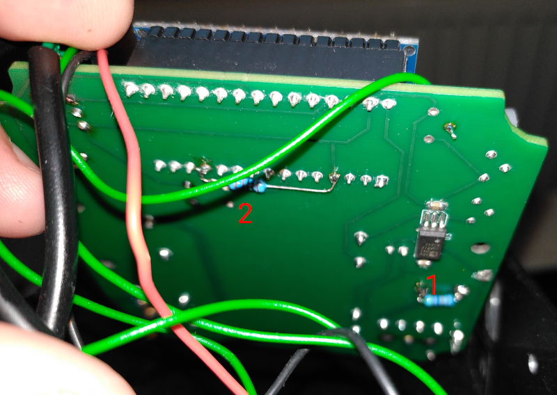 |
Bodge 1 is the bleeder resistor for the DC power supply. That’s a 470kohm resistor to discharge the 47µF capacitor for the 300VDC supply. It is calculated to take about 30 seconds to discharge the 300VDC to a safe (below 50V) level. I really don’t want that thing to be charged when I go to work on Bigfoot’s innards.
Bodge 2 is the pull down for the PWM output. Without that, the motor screams at full power while the Nano is booting. That’s not fun.
There’s a third bodge that you can’t see in that picture. It’s a pull down on the foot pedal connection so that if you turn Bigfoot on without the pedal connected it will stay stopped.
For the curious among you, here’s the updated schematic and layout:
| Bigfoot schematic diagram |
|---|
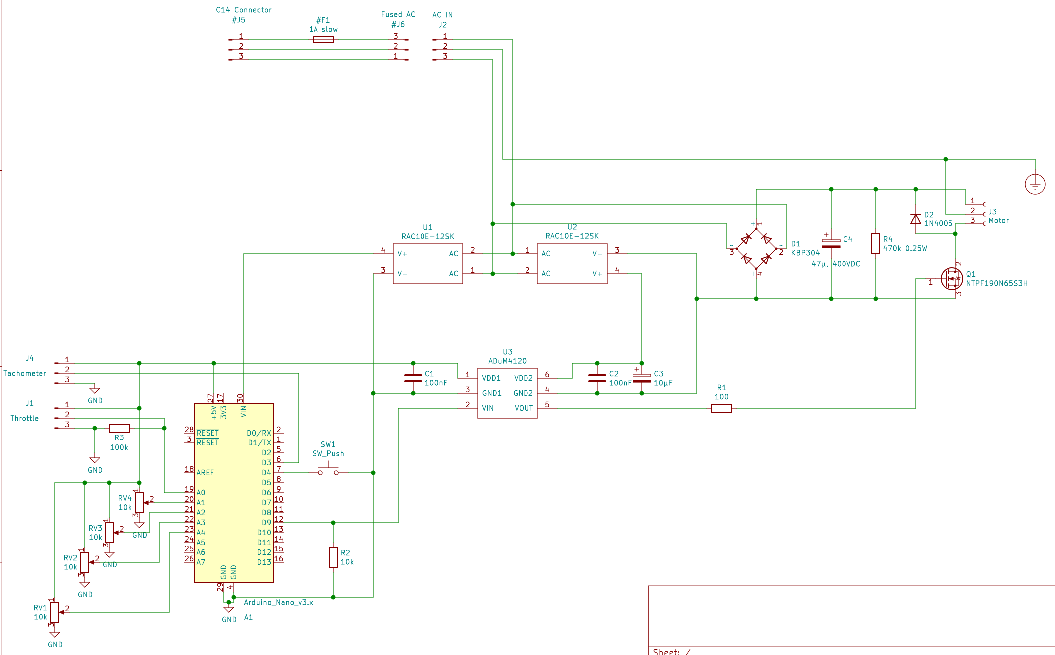 |
| Bigfoot PCB layout |
|---|
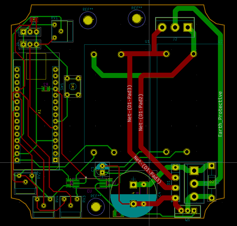 |
The bleeder resistor is still on the bottom side, even in the improved layout. There’s simply no room for it on top.
Electrically, Bigfoot is not all that complicated. The difficult bits are all in the Arduino. Well, that and making a somewhat safe layout to deal with 300VDC and 230VAC.
Stay tuned for more updates on Bigfoot.