A sewing machine motor speed control - When you really need an engineer's help.
Kerplunk. Kablooey.
A sewing machine motor speed control - Table of Contents
I didn’t put any kind of radio interference supression in Bigfoot’s circuitry, so I got to wondering just how badly (or if at all) it interferes with radio reception.
Lacking a radio frequency spectrum analyzer and all the antennas and stuff (and training) to make measurements, I simply got out a pocket AM radio and tuned it between stations and listened while running my Adler under various conditions. That’s sewing light cloth and sewing through several layers of leather, as well as simply dragging my thumb on the handwheel while running the motor at low speed.
It seemed to be fairly quiet - the noise was far less than our hand mixer (that has a universal motor) produces when running. I could even hear radio stations (when properly tuned) which I can’t do when the hand mixer is running. The radio frequency interference from Bigfoot was audible, but not bad.
I was going to record the radio sound of Bigfoot and our hand mixer to let you compare them, but while running Bigfoot at low speed with my thumb on the handwheel, something exploded.
There was a loud bang and my computer lost power - the sewing machine stopped, too, of course.
Something was wrong with Bigfoot.
After unplugging Bigfoot and resetting the circuit breaker in the house, I found that Bigfoot’s fuse had not merely blown, it had exploded. There was nothing left of it but the end caps and some glass splinters.
| Kablooey |
|---|
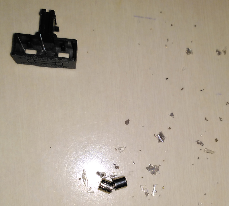 |
I found that Bigfoot’s rectifier, the motor driver MOSFET, and the flyback diode had all failed short circuited.
After replacing them, I fired Bigfoot up again and less than a minute later there was another bang.
Working on the assumption that the flyback diode wasn’t up to the motor current, I replaced what was supposed to be a 1N4007 with a 1N5408 (along with the other dead parts.)
That lasted only seconds before the fuse exploded again.
At this point, I asked the folks on the Electrical Engineering Stackexchange what might be wrong.
I got several good recommendations, and between those tips and being able to actually examine the circuit and the components I believe I’ve begun to understand the problems - and how to fix them.
From what I understand, the most likely cause is that high voltage spikes killed the flyback diode. That diode is actually there to catch the spikes, but if they have a too fast rise time then the voltage can exceed the diode’s rated voltage before it can switch to conduction mode. When the flyback diode fails, it fails short circuited. That kills the MOSFET, which also fails shorted. The shorted MOSFET then short circuits the bridge rectifier (through the shorted flyback diode) which also causes the bridge rectifier to fail shorted.
All of those short circuits cause the fuse to blow. All of this happens faster than the fuse can blow, so the circuit breaker in the house trips at the same time.
What I need is the following:
- A resistor/capacitor snubber to slow down the spikes so that the flyback diode has more time to switch.
- A different flyback diode that can handle more current.
- A fast flyback diode so that the snubber doesn’t have to be all that big.
- A ceramic fuse instead of glass fuse so that short circuits are quenched fast enough that the house circuit breaker doesn’t trip.
- Lower the PWM frequency from 20kHz to 5kHz. The faster frequency is harder on the MOSFET.
- Limit the PWM duty cycle to 70 percent so as not to exceed the power rating of the motor. It is designed for 230VAC. That’s the equivalent of 230VDC. At 100 percent duty cycle, however, it is getting 300VDC. Limiting the duty cycle to 70 percent will limit the equivalent DC to around 230VDC.
- NTC resistor to limit current to the smoothing capacitor in the 300VDC power supply.
- New PCB layout to hold the new parts. I’ll tack things together first to see if the other changes help, then make an improved layout. Besides the extra parts I also need to increase the separation between various high and low voltage nodes.
The bit about the fast flyback diode is probably the reason why it took so long for Bigfoot to blow. I designed it with the intention of using a 1N4007 as the flyback diode. When I assembled it, I had a UF4007 at hand so I used it instead. The difference between a 1N4007 and a UF40007 is that the UF4007 switches in around 75 nanoseconds while the 1N4007 switches in about 1500 nanoseconds. That’s fast enough that the UF4007 managed to catch the spikes for several hours before missing one (or some) and being damaged. I’ll be switching to a UF5408 - it can handle 3A of current while still having a reverse recovery time of 75 nanoseconds.
I’ll use the information from the STMicroelectronics application note AN280 to calculate the resistor and capacitor values for the snubber. The calculations there are based on only the motor voltage, the maximum current, and the reverse recovery time of the affected diodes (and the MOSFET.)
If I were an experienced engineer, I’d have thought of those things before Bigfoot went bang. We’ll see if I’ve learned enough to keep Bigfoot from exploding after I fix it this next time.
Bigfoot ran for several hours on several days scattered over several weeks, and helped me get several projects done.
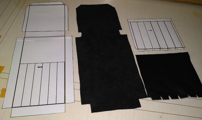
There was the music stand carrying case I made for my wife:
| Music stand carrying case |
|---|
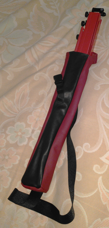 |
There were actually two of those. I made one out of Naugahyde (PVC fake leather) for practice and then the real one of leather.
I also made a new pouch for an old set of files:
| File pouch |
|---|
 |
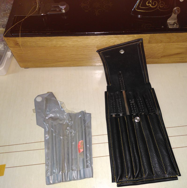 |
My wife asked me to make a new carrying case for a dictaphone that one of the doctors uses in the hospital she works in:
| Dictaphone carrying case |
|---|
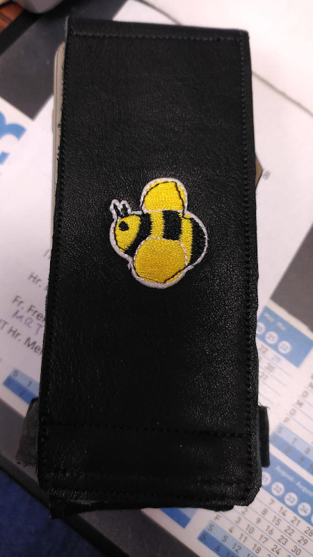 |
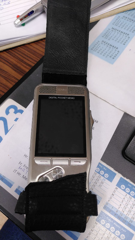 |
I’m not good at this, but I’m getting better.