A sewing machine motor speed control - A snubber for Bigfoot
Protecting the flyback diode that protects the MOSFET.
A sewing machine motor speed control - Table of Contents
I’ve been re-reading STMicroelectronics AN280, and thinking over the requirements and conditions it lays out for a snubber on a DC motor.
As I mentioned before, the main things you need are the following:
- The voltage rise you want to allow
- The time that the voltage rise is allowed to occur over
- The current through the motor
Since those are influenced by the other components in the circuit, here’s a summary of the involved components and selected parameters:
- Power supply: 310VDC
- UF-5408: peak inverse voltage 1000V
- UF-5408: reverse recovery time ($T_{rr}$) 75 nanoseconds
- Motor peak current: ~3.6A ($\frac{DC-power-supply-voltage}{DC-motor-resistance}$)
That last is a problem. While the KBP410G bridge rectifier I have upgraded to is rated for 4A, that’s only when used with a heat sink. I haven’t been able to find a heat sink designed for use with the KBP form factor, so Bigfoot doesn’t have a heatsink for the rectifier. Without a heat sink, the rectifier is only allowed 2A.
I’ll have to redeign the PCB anyway to accomodate the snubber, so I’ll swap the KBP410G for something I can easily put a heat sink on - or maybe a wired one that I can screw to the Bigfoot controller housing.
For now, I’m going to install the snubber on the existing PCB so I can get it running again.
A snubber is simply a resistor and a capacitor in series, with the two placed in parallel across the motor.
It looks like this:
| Snubber |
|---|
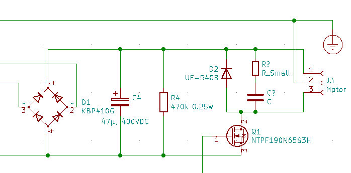 |
The snubber consists of R? and C?, neither of which has (as of yet) a value.
How do you figure out the needed values?
According to AN280, you need to figure out the allowable voltage rise first.
In my case, all of the components have been selected to allow a maximum of 1000VDC. I’m going to allow only 500VDC across the motor (and the diode.)
The resistor value is then: $R = \frac{V_{allowed-peak}}{I_{motor-peak}} = \frac{500V}{3.6A} = 139\Omega$
Next is the capacitor value. The reverse recovery time of the UF5408 is 75 nanoseconds. The rise time of the reverse peak has to be longer than that. I’d like the rise time of the peak to be double that of the diode -that’s 150 nanoseconds.
The capacitance is calculated as follows: $C =I_{motor-peak} \ times \frac{dt}{dv} = 3.6A \times \frac{150ns}{500V} = 1.08nF$
With both values in hand, the next step would be to calculate the power dissipated in the resistor.
According to AN280, the power dissipated in the snubber resistor is given by this formula: $P_d = (I_1^2 \times R \times DC) + (I_2^2 \times R \times DC)$
In this formula, DC means “duty cycle.” The maximum duty cycle will be 70%. That’s 0.7. The reason behind that is so that the motor receives approximately the same RMS voltage from the 310VDC supply as it would have when run on 230VAC. The application note then says it is ignoring the the duty cycle and sets DC to 0.01.
$I_1$ and $I_2$ are the current at turn on and turn off. AN280 is dealing with a different motor control where the currents are different. In the Bigfoot control, the currents will be the same so the formula simplifies to: $P_d = 2\times(I_{motor-peak}^2 \times R \times DC)$
The power rating for the snubber resistor is then: $P_d = 2\times(I_{motor-peak}^2 \times R \times DC) = 2 \times 3.6A^2 \times 139 \times 0.01 = 18W$
That is not realistic. Either I’ve bungled things completely, or there’s something wrong with the power calculation in that application note.
Other snubber calculators (such as this one at DayCounter) calculate the power according to a different formula: $P = (\frac{1}{2} \times C \times V^2) * f$ where C is the capacitance and f is the switching frequency. For the values above, that comes out to $P = (\frac{1}{2} \times 1.08nF \times 310^2) * 5000 = 0.26W$
All together:
- Capacitor value = 1nF.
- Resistor value = 139 ohms, rated for more than 1/4 watt.
- Both parts require a voltage rating comparable to the UF-5408.
- I will have to lower the switching frequency from 20kHz to 5kHz.
- The PWM output has to be limited to 70 percent maximum.
I’ve placed an order for some 1nF, 1000V ceramic disc capacitors and some 61.9 ohm resistors rated for 400VDC. I’ll put a couple of them in series to get a higher voltage rating and a total resistance of 124 ohms. That’ll bring the peak voltage down a bit. The combination of two resistors 1/4 watt resistors in series spreads the dissipation across the two of them - that’s like having a half watt resistor.
| Finished snubber |
|---|
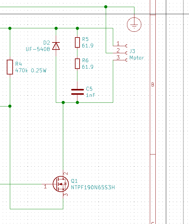 |
The parts may take a while to get here. I ordered them from Mouser, and Mouser says they’ll be shipping them international to me in Germany.