A sewing machine motor speed control - A MOSFET source follower as a motor speed control
Better, but far from good.
A sewing machine motor speed control - Table of Contents
The simple motor controller I looked at the last time around was really just an electronic equivalent to the mechanically switched resistors commonly found in sewing machine foot pedals. It is a “stupid” circuit in that it doesn’t make use of the possibilities granted by the transistor used in it.
The biggest drawback of that type of simple control is that it robs the motor of power. Any load at all on the motor will cause it to slow down.
If you rearrange the parts slightly, you get a much improved control.
| Somewhat better motor speed control |
|---|
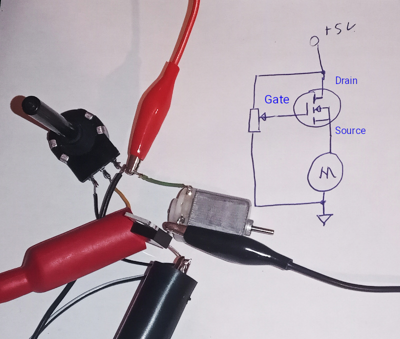 |
That uses the same parts, but rather than using the MOSFET as a simple variable resistor, I’ve wired it as a source follower or a common drain circuit.
The nice thing about the source follower is that the voltage at the source follows the voltage on the gate. The MOSFET actively works to maintain the source voltage at (or at least, close to) the gate voltage.
For the motor control, this means that the MOSFET will attempt to maintain the set voltage by increasing the motor current as needed. When the mechanical load on the motor causes the motor to slow down, the MOSFET jacks up the current to make the motor run faster.
The simple circuit I demonstrated in the last post doesn’t do that:
As you can see, the current doesn’t change to match the changing load.
The source follower circuit does a much better job:
The source follower runs up the current when I load the motor - it is trying to maintain the motor speed.
Despite being better, the source follower is not good enough:
- There is a maximum gate to source voltage allowed by the construction of the MOSFET - using it with the much higher voltage of the sewing machine motor would be difficult (at least, for me it would be.)
- There is always a couple of volts of difference between the gate and the source. This is due to the way that FETs work. The gap eats into the control range. For the low voltage circuit I’m playing with, that means that the motor will never get close to its full speed when controlled by the source follower.
- The FET is still being used as a variable resistor. It gets hot even with the low voltage and current I’m using in my experiments.
Any of those three points would be a problem with my sewing machine control. All together they are a “show stopper.” I won’t be making a sewing machine control with a source follower, even though it does illustrate how to get feedback to maintain a set speed.
Fixing points 1. and 2. means using the MOSFET on the low side - that is, with the source connected to ground and the gate voltage limited to something below the maximum V_GS for whatever MOSFET I might use.
Fixing point 3. means a radical change. I’ll go into it in my next post.