A sewing machine motor speed control - A simple pulse width modulation driver as a motor speed control
One step forward and one step back.
A sewing machine motor speed control - Table of Contents
In my last post, I mentioned that fixing the heating problem in the MOSFET called for a radical change in direction. That change in direction is so drastic that I’m going to go back to an open loop control.
The cause of the heating is that the previous two examples have both used the MOSFET as a resistor. Anytime current flows through a resistor, there’s heat generated. There’s less heat generated when the resistance is low, and less heat generated when the current is low (or off.)
Therein lies the solution. Rather than using the MOSFET as a variable resistor, I’m going to simply switch it on and off rapidly. When the MOSFET is fully off, no current flows so there’s no heat generated. When the MOSFET is fully on, its resistance is very low - again generating very little heat.
To control the speed of the motor, you vary the proportion of time the MOSFET is conducting.
This whole scheme is called pulse width modulation (PWM.) It’s not something I’ve thought up myself, it is a standard and commonly used thing.
PWM is what Arduino folks refer to as an analog output. Arduinos don’t have a real analog output, they just have pulse width modulated digital outputs that can be used to (crudely) generate analog signals.
I’m going to use a PWM output from an Arduino Nano to drive the MOSFET and control the motor speed.
| PWM motor speed control circuit |
|---|
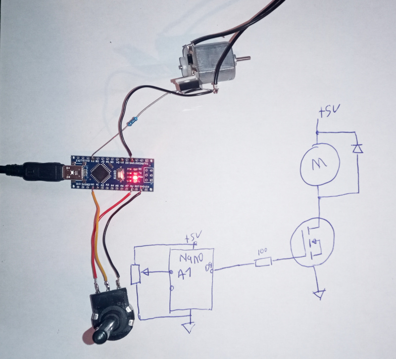 |
The software is trivial:
#include <TimerOne.h>

#define PWM_PIN 9
#define period 50 // 50 microseconds = 20kHz

void setup() {
  pinMode(PWM_PIN, OUTPUT);
  Timer1.initialize(period);
  Timer1.pwm(PWM_PIN,0);


}

void loop() {
  int analogValue = analogRead(A0);

  Timer1.pwm(PWM_PIN, analogValue);

  delay(5);
}
I’m using the TimerOne library because it allows higher pulse width modulation frequencies than the standard Arduino “analogWrite” command. It also allows finer steps. The standard Arduino PWM has 255 steps. TimerOne uses 1023 steps, which makes it a snap to control with the potentiometer. The higher frequencies let it run without an audible “squeal.” At low speed and a low PWM frequency, motors make an audible noise - you don’t want to listen to “squeeeeee” all the time while sewing.
The potentiometer varies the voltage from 0V to 5V. The Arduino has a 10 bit analog to digital converter - the values vary from 0 to 1023 over the 0V to 5V range. Read the analog input once in a while, write the same value to the pulse width modulation output. Easy.
| PWM at low speed |
|---|
 |
| PWM at high speed |
|---|
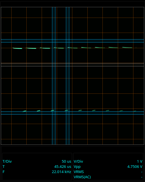 |
As you can see, the pulses are evenly spaced. Only the length of each “on” pulse varies. When the pulse is longer, the motor gets more power and runs faster.
This form of control has the advantage of not heating the MOSFET unnecessarily. This circuit doesn’t include any form of feedback to maintain a set speed, but it could be implemented with a little more work.
Another advantage that it has is that it delivers full voltage and current to the motor coils on each pulse. The motor has more torque at low speed than it does when controlled by a variable resistor. That doesn’t quite make up for the lack of feedback, but it does make things run better - and even more so when you add in some feedback.
The next step is to add in some feedback so that the Arduino can make the motor maintain a set speed. I’ll implement that for my next post.