A sewing machine motor speed control - PWM + PID + current measured BEMF = Fail
A failure and a new plan.
A sewing machine motor speed control - Table of Contents
I haven’t posted anything for a while. I’ve spent several evenings tinkering with my little motor and the Arduino controller, but haven’t been able to get them to do what I want. I have pretty much come to the conclusion that what I want isn’t possible.
I’ve been trying to get a stable, slow motor speed using feedback from the back EMF of the motor. I’ve not been able to get it stable, smooth, and quick. I either get twitchy but quick to adapt to load changes or I get smooth but too slow to react to load changes.
I’ve been reading up some, as well. It seems that speed control through BEMF doesn’t work well at low speeds, and that measuring BEMF via the motor current doesn’t work well at low speed, either. The feedback is unreliable and noisy, and that drives the PID controller crazy.
For reference, here’s the circuit I’ve been fiddling with:
| Current feedback controller |
|---|
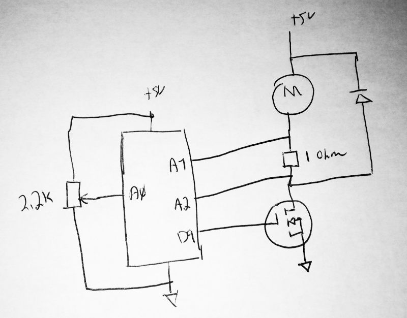 |
It looks a lot like the voltage feedback circuit I used in my last post, but instead of measuring the voltage across the motor, I’m measuring the voltage drop across a 1 ohm resistor in series with the motor. From the voltage and the known resistance I can figure the current. From the current and the known motor resistance (1.5 ohms) I can calculate the voltage across the motor.
Since the current shouldn’t change much, I thought I’d be able to measure the current without stopping the PWM. It sort of works, but there’s too much noise from the commutator in the motor. The measurements are too noisy to use, and filtering them slows the reaction of the PID controller. You get either noisy and jumpy (the speed goes up and down all the time at random) or you get somewhat smooth but so laggy there’s no point in using the PID controller - the simple, naive controller I first used was slower but smoother and better behaved than the PID controller.
I’m not going to post a video - there’s not much point in watching a motor do random things.
It looks like I’m going to have to whip up some kind of better speed detector. It’ll have to be something that provides a clean signal and that keeps working even at low speed. Maybe a Hall effect sensor with a magnet stuck to the motor shaft, or maybe an optical setup with an infrared emitter/detector pair with slotted disk on the motor shaft.
Using an external sensor has the added advantage of simplifying the high voltage section. Working with the back EMF was going to involve measuring up to 300 volts DC, or currents up to a few amperes on the high voltage side. With an external sensor, the only thing on the high voltage side is the FET and the FET driver.
I’ll be ordering some small parts in the next days to build a new controller.
Stay tuned for updates and progress reports.
This kind of result is the reason I like to start my projects small then work up to the real thing. It would have been a waste and an aggravation to jump straight to a controller for the sewing machine motor (with the cost of parts and a custom PCB) only to find that it doesn’t work well enough. This “failure” with the small motor only set me back a couple of bucks and some time experimenting. It has also taught me a lot about PID controllers and given me a feel for what they can and can’t do.
Fail fast, fail small, repeat for large gains and low cost.