Counting RPM with a photointerrupter
When things don’t work like they ought to.
While experimenting with motor speed controls for a planned motor controller for my vintage Adler class 8 sewing machine, I found I needed a better method to detect the rotational speed of the motor. The methods I was using (based on measuring the back EMF of the motor) were not doing well at the low speeds I need.
To get accurate RPM counts at low speeds, I decided to try counting the RPM using a photointerrupter. This will mean adding hardware to the motor (which I wanted to avoid.) The required hardware is the photointerrupter along with a slotted wheel on the motor axle.
I ordered a set of cheap photointerrupters from Amazon because they came with slotted wheels and a small circuit board. They are ideal for experimenting.
| Photointerrupter module |
|---|
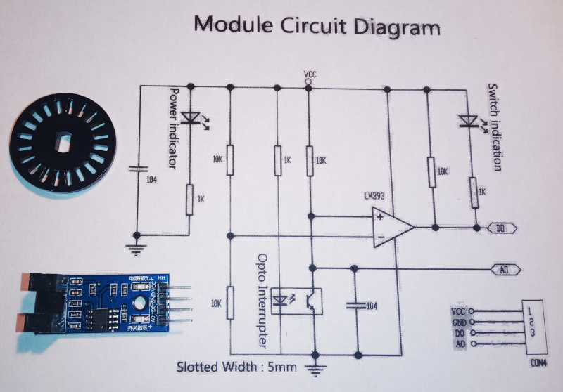 |
| The circuit diagram is from the Amazon page for the Youmile modules I ordered. |
I attached the slotted wheel to one of the little motors I’ve been using and setup the photointerrupter to have a look at the signals.
| Test setup |
|---|
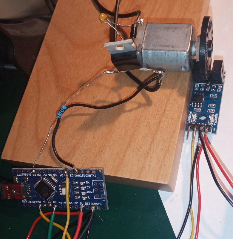 |
Once it was all wired, I turned on the juice and looked at the oscilloscope - nada. Nothing. No pulses. The motor was whirring away, but there were no pulses on the digital output of the module.
The wiring is simple enough that it only took a quick glance to see that it was OK.
I connected the scope to the analog output of the module, and got something like this:
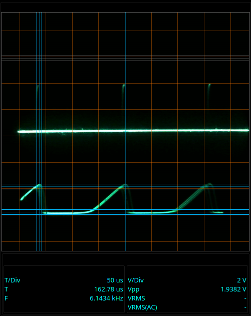
| Shark fins |
|---|
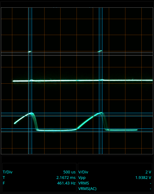 |
| About 1400 RPM |
The lower trace is the analog output. Given the shape of the slots, I expected that even the analog output would be somewhat square and symmetrical. I sure didn’t expect rounded off “shark fins” whose amplitude varied with the motor speed.
At high speeds, the amplitude of the photointerrupter pulses (on the analog output) are too low to trigger the LM393 comparator. The circuit diagram shows that the comparator triggers when the photointerrupter signal goes above half the operating voltage - that’s a 2.5V trigger level for the 5V power supply from the Arduino.
Besides not triggering at high speed, the pulses also weren’t square and symmetrical. They got narrower as the motor sped up until they disappeared altogether.
The pulses are wider at low(er) speeds, but still not what I’d expect.
| Slower shark fins |
|---|
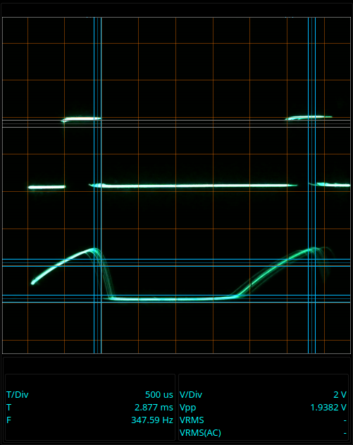 |
That’s not what I bought the modules for, so I had a good look at the circuit diagram. I bought the modules I did specifically because the seller included a circuit diagram on the page advertising the modules.
| Guilty parties |
|---|
 |
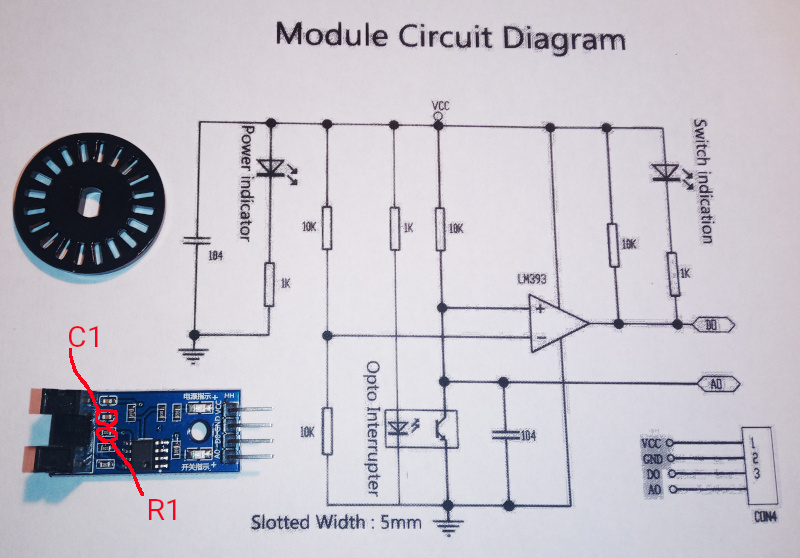 |
The circuit diagram also shows why the photointerrupter signal looked like a shark’s fin. There’s a 100 nanofarad capacitor (C1) across the phototransistor. Together with the 10k resistor (R1,) C1 forms a low pass filter with a cutoff of around 160Hz. Given that there are twenty pulses per rotation, that means that the filter starts distorting the signal at around 480 RPM. At about 1500 RPM, the signal is so distorted that the comparator can no longer detect it - the digital output goes flat.
I removed C1, which improved things considerably. The comparator got a good signal up to around 18 thousand RPM - but still with shark fins.
| Improved |
|---|
 |
| About 18000 RPM |
The phototransistor in the photointerrupter has some capacitance so there’s still a little low pass filtering going on.
I reduced R1 from 10k to 750 ohms, and finally got the clear, sharp square waves I expected.
| Clean signal |
|---|
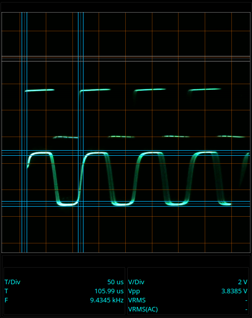 |
| About 23000 RPM |
The analog output is very nearly square, and the digital output from the comparator is sharp and symmetrical.
It works at lower speeds just as well.
| Lower speed |
|---|
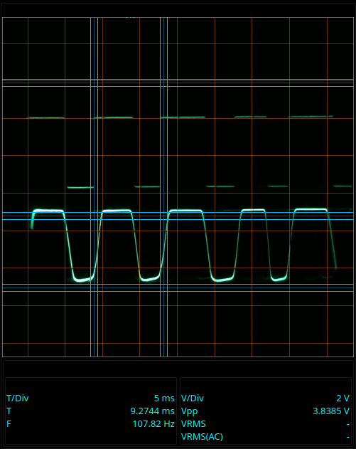 |
| About 325 RPM |
That’s at the lower end of the RPM range I’ll need for the sewing machine.
I’m aiming for a low speed of about 1 stitch per second on the sewing maching. The way the Adler 8 works, that means that the hand wheel turns once per second - 60 RPM. There’s a six to one pulley ratio from the motor to the hand wheel, so the motor has to turn at about 360 RPM for the machine to do one stitch per second. That ratio also means that the 1500 RPM limit mentioned above would work out to 250 stitches per minute. That’s a little on the slow side, even for me.
I want the low speed for precision stuff (intricate, decorative stitches,) but at the same time I need to be able to “floor it” and sew straight, simple stuff quickly. The original state of the photointerrupter module would have covered the low end of what I need, but not allowed for the higher speeds.
Here’s how you calculate the RPM.
- Measure the time between two rising edges - that’s $t_{pulse}$. Make sure to use seconds, not milliseconds.
- $RPM = \frac{60}{20 \times t_{pulse}}$
If you try to calculate the RPM from the pictures above, watch the units. The cursors mark the time of one pulse. That time period is shown in the measurements section. Sometimes the time is in milliseconds, and sometimes it is in microseconds. You have to convert to seconds to calculate the RPM.