A simple signal generator
Making your own tools.
My Telequipment D43 projects - Table of Contents
When I finally got my Digital D43 oscilloscope camera software to a point where I could use it, I found I needed a way to check it for accuracy - and the old D43, too.
All it takes is a reasonably accurate signal of a known frequency, and a known voltage.
DC voltages are easy - just measure some random battery with a voltmeter and compare to what the scope says.
Frequencies are a different matter.
I don’t own a good signal generator. It’s just never been needed. Most of the stuff I do is either working with existing, live signals (like my acoustic heartbeat detector algorithm or the noise filter.) Or, it’s with signals that I’m not going to be generating with any kind of home made stuff (like the satellite dish RF camera.)
I thought about it for a bit, and remembered that I had a bunch of Arduino Nanos stashed away somewhere. That’s the way out.
You’re probably thinking “Arduino” and “precision” and coming to the conclusion “oxymoron.”
Yeah. In comparison with a modern oscilloscope I’d agree. I’m not talking modern, though. I’m talking 1965, and tubes.
The old D43 doesn’t do precision. It’s to look at stuff, and make some half way reliable estimates about what’s going on. As the Germans say, it is a “Schätzeisen.” It isn’t wrong, it just isn’t exact.
The uncalibrated clock in a Nano of questionable heritage is guaranteed to be more exact than the scope, and exact enough to judge the accuracy of measurements made through a webcam.
There are many tutorials on the web with examples for generating square waves, but many use the Arduino delay functions. I don’t need extreme precision or extremely high frequencies, but the delay generated signals are too sloppy - even for my really laid back requirements.
The correct way to do the job is to use a timer. I rooted around the internet a bit, and located the Arduino Timer1 library. That’s about the easiest way to handle the timers.
In less time than I’ve spent telling you about it, I had a simple program to generate 1kHz square waves. A half an hour after that, I’d added a simple serial protocol so that I could change frequencies without recompiling. 32Hz to 1MHz, serial control. Easy peasy.
Once the software was done and working, I checked the frequency accuracy on my D43. Pretty sad, to tell the truth. Voltage and frequency are off by about 4% on all ranges. And, all the ranges are off a little bit different - well, of course they are. The timing is set by a bunch of discrete capacitors in the timebase circuit. They are all 10% parts (at best) and have most certainly drifted in the 50 years since the D43 was built.
Now, how do I keep this thing from getting lost in among all the other Nanos?
Put it in a snazzy housing. Hmmpf. I finished it on a Sunday, and I live in Germany. Damn few stores open, and none that sell electronics stuff.
Well, I have a garage full of wood scraps and hand tools. Just make one and be done with it.
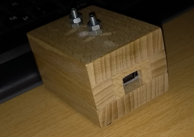
Looks like this:

Hmmm. That sort of misses the mark on “snazzy,” but it is functional. You know, it took longer to make the housing than it did to write the software.
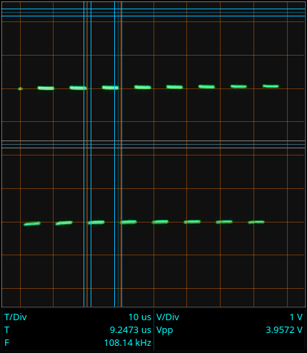
Here’s a picture of its output as captured by my camera software:

Jeez! Off by 8% on the frequency! That’s a 100kHz signal there. I really need to get out the service manual and calibrate and/or replace the capacitors in the timing circuits of the old D43.