Soil moisture monitoring in a flower garden - Solar power for the monitoring system
Assembling a few modules.
All about my experiments in soil moisture monitoring - Table of Contents
It’s been a while since I last wrote about my plans to monitor the soil moisture in my flower garden. Fall and winter came, and it wasn’t pressing. I’ve been doing things that I could do in my hobby room, and having fun.
We had a few days of really cold weather, then it turned warm. I’ve got crocuses and narcissuses (yes, that’s the proper plural - I looked it up) poking up out of the bark in the garden. The yellow and white blossoms reminded me that I had a project on the back burner.
I bought a few solar charged power banks a few months ago with the intent to use them to power the ESP32S modules I’m going to use to collect the soil moisture data from the sensors. Plug the ESP32S modules into the power banks, then let the modules sleep most of the time.
That unfortunately doesn’t work. The power banks shut off the 5V output boost converters when the load is too low.
I kept trying to think of a way to make the power banks stay on or power the low power processor on the ESP32S modules from a coin cell or something and have it “wake up” the power bank and then the main processor. I didn’t like any of the Rube Goldberg combinations of hardware and software I kept coming up with - too complicated and too prone to failure.
I wanted something simple and reliable, and couldn’t come up with anything - until a few days ago.
A few days ago, there was a question on the Electrical Engineering StackExchange about how to power a nRF24L01. Somebody was looking for a low power 3.3V regulator to extend the run time of their gadget. The person asking somehow thought that a Zener regulator would be less wasteful than a low drop out linear regulator or a buck converter.
My suggested solution was to use an LM3671 3.3V switching regulator module. The LM3671 is a buck converter with a quiescent current of 16 microamperes. It switches to a skip mode and consumes very little current when there’s no load.
According to Adafruit (who sells such a beast,) the LM3671 3.3V module will regulate the output voltage as long as the input is above 3.3V, and below that it will track the input voltage (minus a couple of hundred millivolts.)
I realized that I had found the solution to my problem.
The solar charged power banks use a single 3.7V lithium ion cell.
According to this Adafruit article, the voltage from a 3.7V lithium ion cell should stay above 3.3V until it is almost totally discharged, especially at low loads. The ESP32S modules will be sleeping most of the time, so they will be very low loads indeed.
I’m going to use the LM3671 to regulate the lithium cell voltage directly, completely bypassing the 5V boost circuit in the power bank. The ESP32S can accept a 3.3V power input, bypassing its own 3.3V regulator.
My power banks have a “lighter” port - literally a lighter, for lighting things on fire.
I’m going to remove the heater coil and install the tiny little LM3671 module in its place.
The battery protection circuit is conveniently located, so I can tap the battery power after the low voltage protection circuit - my extra little regulator won’t be able to kill the lithium cell.
The connections to the ESP32S can come out through the lighter port.
I spent a little time this afternoon verifying how the LM3671 operates.
- The LM3671 shuts off completely when the input voltage drops below 2V.
- With a 10 ohm load, the LM3671 output voltage tracks about 150mV below the input voltage up to 3.5V.
- Above 3.5V in, the LM3671 output voltage is regulated to 3.3V.
The ESP32S will operate on about 2.3V to 3.6V. Really, all it needs is protection against over voltage from the battery. The LM3671 makes sure the ESP32S is never exposed to more than 3.3V, and the ESP32S will be happy until the low voltage protection from the power bank kicks in.
I have three ESP32S modules, three solar charged power banks, and three LM3671 modules sitting here, ready to be assembled - but I can’t put them together yet. I forgot to order fuses when I ordered the LM3671 modules. I’ve got some PTCs on order now. They should get here this week sometime, then I can set about modifiying the power banks.
I’ll be fusing these guys together to make my sensor monitoring network:
| Monitor components |
|---|
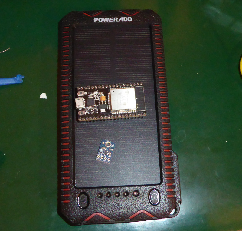 |
The final setup will have the LM3671 inside the power bank with the ESP32S tethered by a short cable. Besides power to the ESP32S, the tether will also deliver a battery monitor signal so that I can be sure the power banks are staying charged.
Despite this thing going out in the yard, I’m not going to waterproof it.
The current plan is to install the whole shebang on a post, then plop a big, empty, plastic bottle over it. All of the gadgets will be literally “high and dry” under the top end of the bottle.
I’ll make photos and explain how the LM3671 can be safely connected to the power bank innards when I get the fuses. Maybe next weekend.
All about my experiments in soil moisture monitoring - Table of Contents