The Adler class 8 sewing machine - The thread tensioning mechanisms
A lot simpler than it looks - but still complicated enough.
Click here to see all the Adler class 8 posts.
There are five components that regulate the thread tension on an Adler class 8 sewing machine. Since the same components are present on other Wheeler and Wilson 9 derived machines, I’ll be using the English vocabulary from the Jones’ Spool user’s guide (from the International Sewing Machine Collectors’ Society collection of Jones user’s guides) rather than try to translate the German language from the Adler class 8 user’s guide I normally work from.
Given the similarities between the various Wheeler and Wilson 9 derived machines, you may find this look at the thread tensioning useful for other machines. There’s the Jones’ Spool (of course,) and the Phönix class 8. I’ve seen mention that FAVTA made a similar machine. Adler used the same basic design on several machines, as well. The Adler 86 and 87 used much the same setup, despite being zig-zag machines. The Adler 187 seems to be related. I’ve also found hints to the effect that Junker und Ruh made a Wheeler and Wilson 9 style machine.
I’ve had cause to disassemble and reassemble all parts of the tensioning mechanism several times over the last few months. The first time around was when I initially cleaned up the machine. Since then, I’ve had it apart several times - looking for problems, more intensive clean up, oiling, etc.
They look like this when properly assembled:
| Upper thread tension components |
|---|
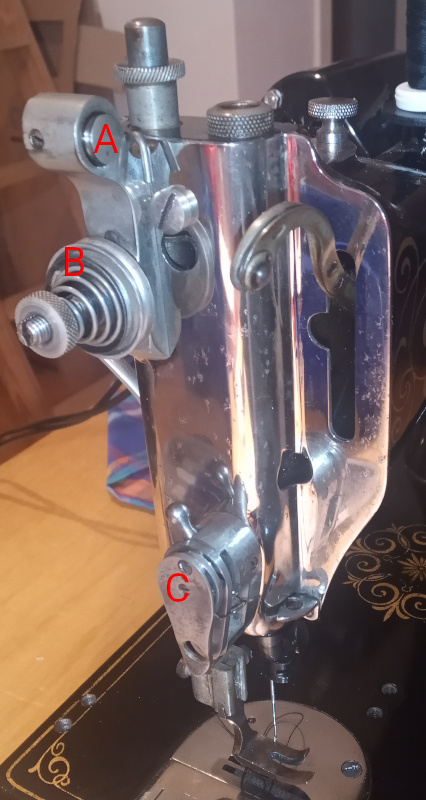 |
| Letter | Name | Description |
|---|---|---|
| A | Thread check | Guides the thread down to the main tensioner and provides a small amount of tension. Also called a “pretensioner.” |
| B | Main tensioner | The nut controls the pressure on the two discs. This is the main tension adjustment for the upper thread |
| C | Thread controller | Guides the thread up to the take up arm. The spring keeps the thread taut while the take up arm is moving. |
If your machine is grungy and gummy, you’ll want to disassemble all three of those components and clean them up. That means getting rid if the grime and dried on oil, but it also means polishing them smooth.
| Lower thread tension components |
|---|
 |
 |
 |
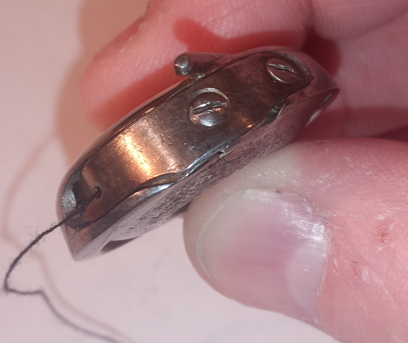
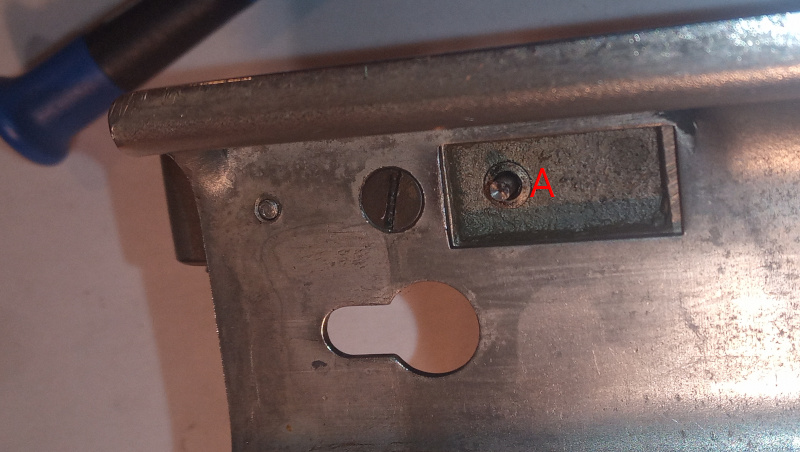
The bobbin tension is adjusted just like on any other sewing machine - the little screw presses the spring against the case to regulate the tension.
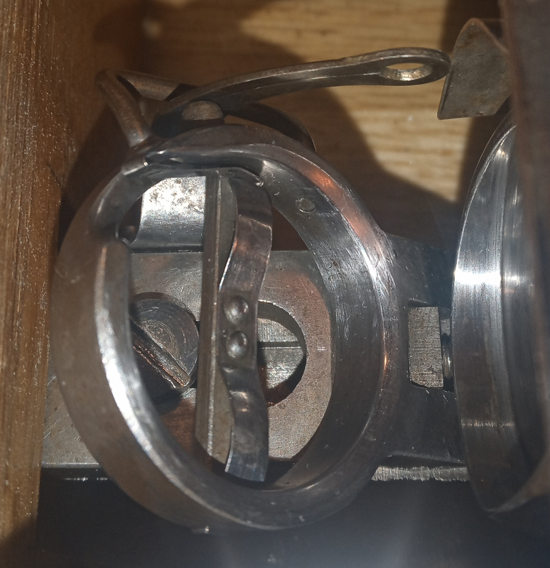
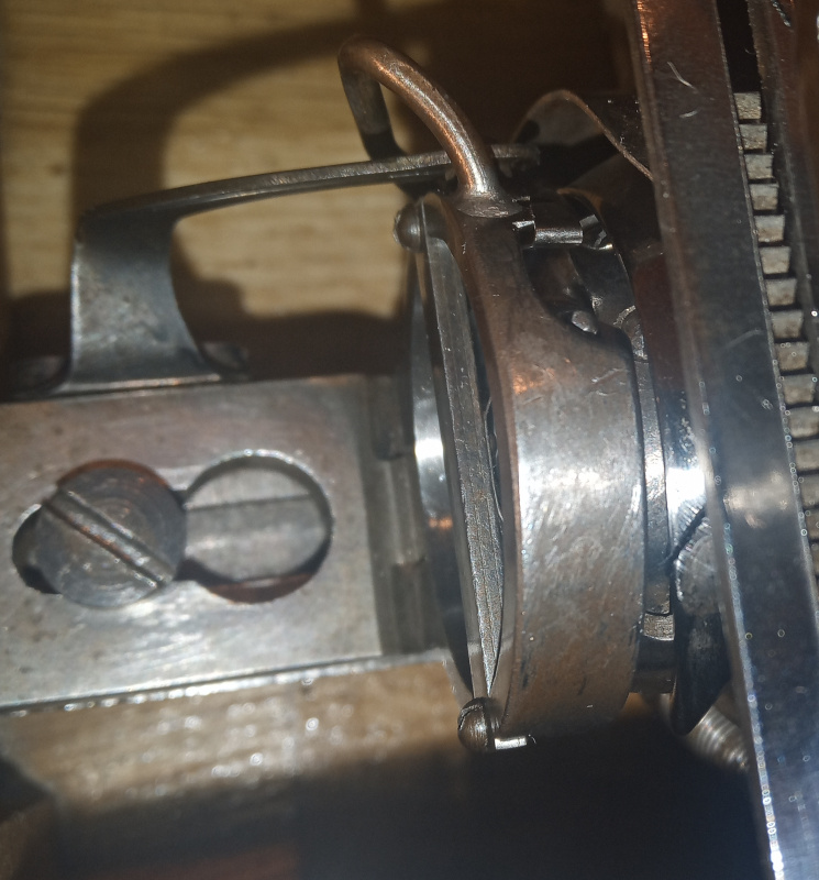
The other two pictures are of what the Jones’ Spool guide calls the “spool holder.” The bobbin case in this type of machine isn’t held in place by an axle like on many other machines. It floats between the spool holder and the rotary hook. You have to adjust the gap between the holder and the hook to be tight enough that that thread is in the right place but loose enough that the thread can pass between the bobbin case and the spool holder.
Let’s take a closer look at the upper thread tensioning components.
In each case, I’ve started with the component disassembled. The photos show how they go together. After each set of photos is a description of how they work or things I’ve discovered about them.
| Thread check |
|---|
 |
 |
 |
 |
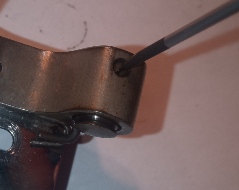 |
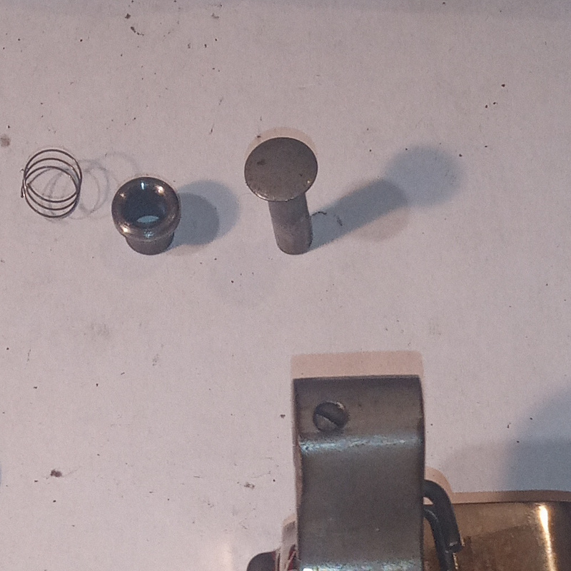
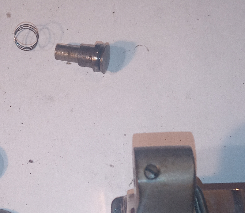
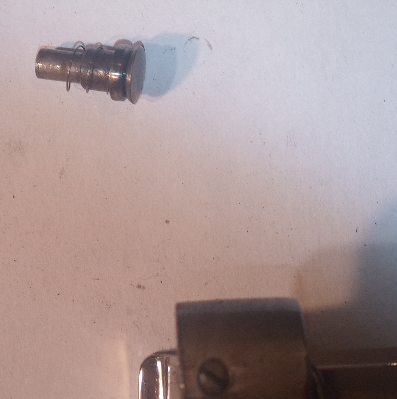
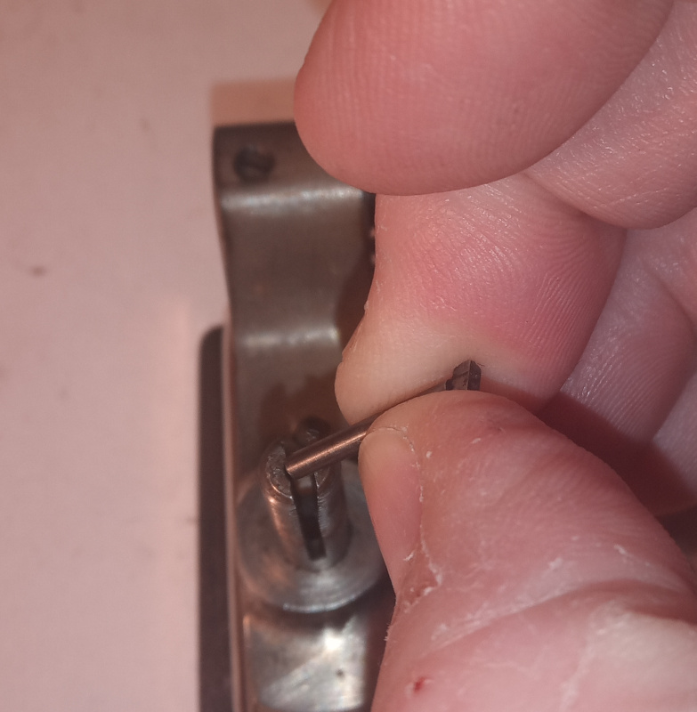
The thread check is composed of a pin, a tube, a spring, and a mounting hole in the body of the main tensioner.
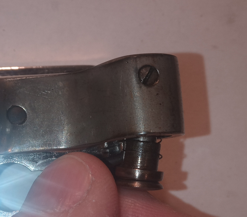
Assemble it as shown, then slide it into its hole in the main tensioner. Align the gap between the head of the pin and the tub to be in line with the hooked thread guide you see in the image below the assembled thread check then tighten the screw. That puts the thread in the proper place to go on down to the main tensioner. It is also the correct tension adjustment.
| Main tensioner |
|---|
 |
 |
 |
 |
 |
 |
 |
 |
 |
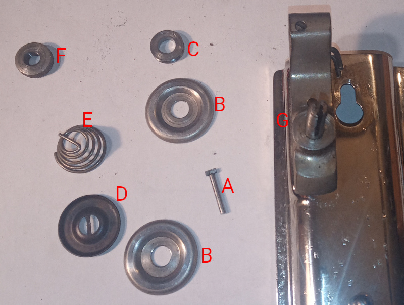
| Letter | Name | Description |
|---|---|---|
| A | Tension release pin | Pushes the tension discs apart when the presser foot is up to release the thread tension. |
| B | Tension disc | The friction between the thread and the wide rings on the discs provides the thread tension. |
| C | Thread pulley | Goes between the tension discs. It prevents the thread from rubbing on the threaded rod that holds the tensioner together. |
| D | Pressure plate | Used to evenly distribute the pressure from the spring on the tension discs. It is also part of the tension release mechanism. |
| E | Tension spring | Provides the pressure needed for the tension adjustment. |
| F | Tension nut | Tightens the spring to adjust the tension. |
| G | Main tensioner mounting block | Holds all the pieces of the main tensioner and the thread check together. It is attached to the face plate with one screw and a pin. The pin aligns the block so that it is parallel to the edge of the face plate. |
On some machines, the two tension discs are a single unit with the thread pulley inside. Do not try to take the discs apart on those machines.
You will often see felt discs that go with the tension discs. Those seem to belong on machines where the tension discs are a single unit. If your machine has separate discs then you don’t need the felt discs. I know mine doesn’t need the felt discs because the tension release pin doesn’t work when there are felt discs in place. It is exactly the length it needs to be. If I put felt discs in there, then the whole stack up is too thick and the tension release pin can’t reach the pressure plate - my Adler 8 doesn’t need felt discs.
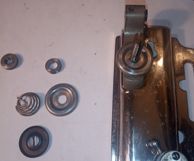
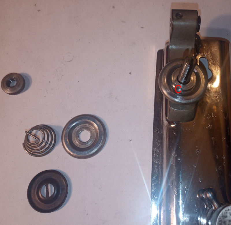
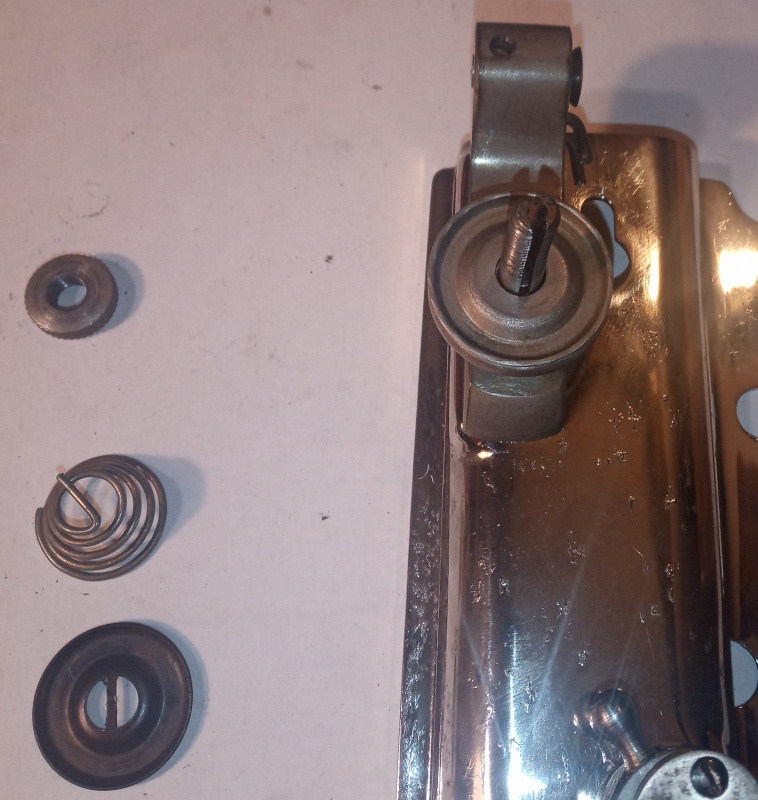
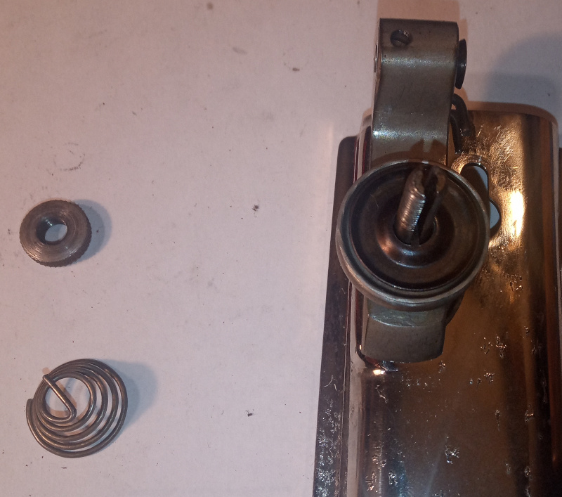
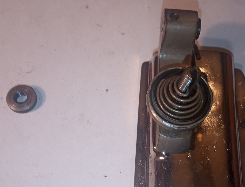
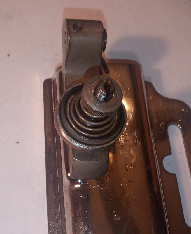
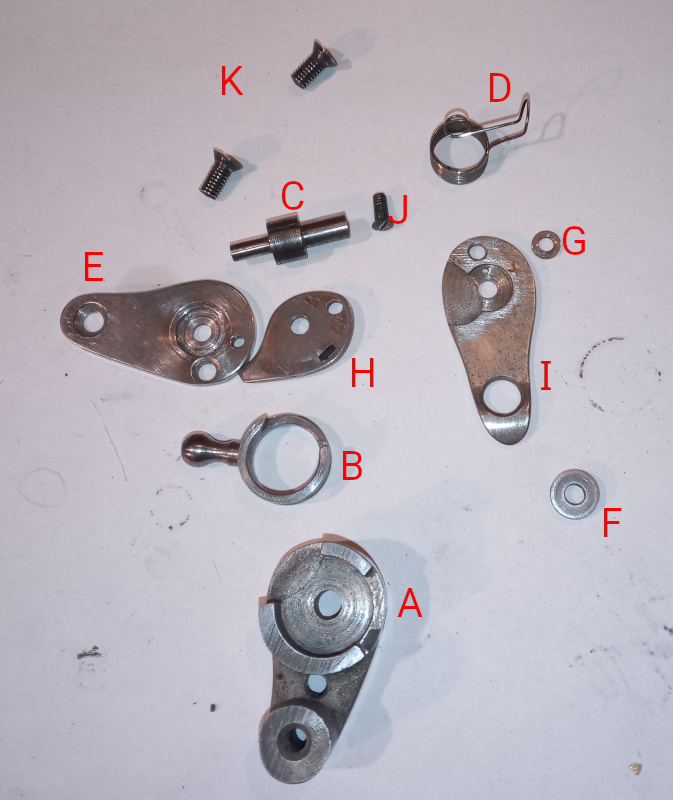
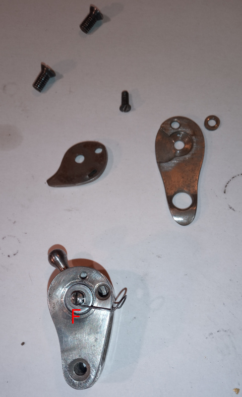
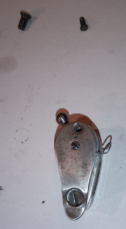
| Thread controller |
|---|
 |
 |
 |
 |
 |
 |
 |
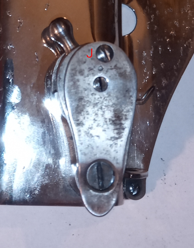 |
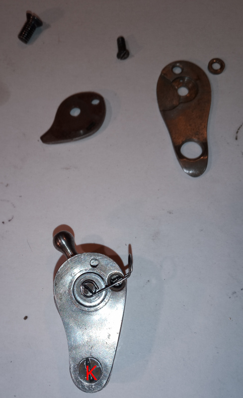
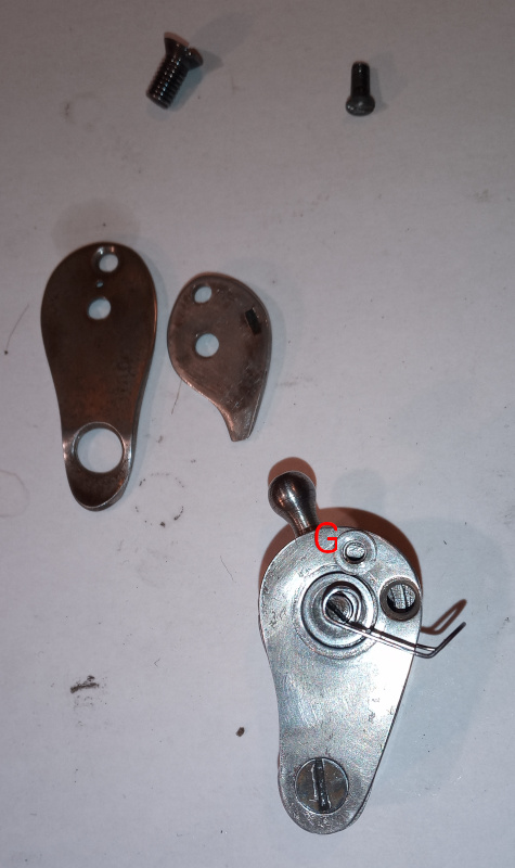
| Letter | Name | Description |
|---|---|---|
| A | Thread controller housing | |
| B | Control lever | Adjusts the travel of the spring. |
| C | Axle | |
| D | Spring | Keeps the thread taut when the take up lever is moving. |
| E | Pulley cover | |
| F | Thread pulley | There is no tension on the thread. The pulley is just to help the thread move smoothly. |
| G | Spacer | |
| H | Thread guide | The hook keeps the thread from falling out of the controller when threading the machine. |
| I | Controller cover | |
| J | Small screw | Holds the cover on the controller. |
| K | Large screw | One hold the controller on the face plate. The other holds the pulley cover in place. |
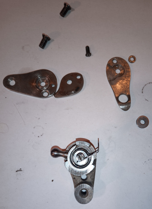
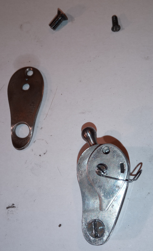
I skipped a couple of photos while assembling the thread controller. The spring goes on the axle. There’s a groove in the axle and a tab on the spring that goes in it. Put the spring and the axle together. Put the control lever in the housing, then put the axle and spring inside the ring on the control lever - there’s a hole in the housing that the thick end of the axle goes through.
The thread controller doesn’t actually put any tension on the thread. It is there to direct the thread up to the take up lever. The spring helps to maintain a constant tension while the take up lever is moving.
The most important thing for the thread controller is that it has to be smooth. The thread pulley should move without sticking or pulling, and the spring should move freely.
I had to polish the insides of my thread controller with 600 grit sandpaper, then with a small polishing wheel and jeweler’s rouge to get things smooth enough.
Oil the moving parts as you assemble them. Just a drop of oil on each moving part. If you get too much in there it’ll get oil all over your thread. If you don’t get enough oil in there then it won’t move smoothly.
Don’t worry about adjusting the spring or the main tensioner just yet. Assemble them correctly. I’ll explain how to adjust them in a later post.
There’s not much point in showing more pictures of the lower thread tension parts - all there is to see is in the pictures up above.
I really wish I could have found a set of detailed assembly instructions or at least detailed photos before I started working on my Adler. It would have made things much easier.
The next post will be about adjusting the tension on the upper and lower thread.