A voltage multiplier and a crazy idea
Re-modulating the subflexive fasarta.
Voltage multiplier experiments - Table of Contents
Due to the COVID19 pandemic, I’ve been working from home the last few weeks like many other folks. I’m a programmer, so I can do pretty much anything from home that I could do in the office.
One thing I can do when working at home that I can’t do while working in the office is to rock out like a maniac to my favorite music.
Whilst programming and rocking out the other day, I realized I need some better speakers. The little bluetooth portable speaker I have in my work room just doesn’t do justice (or volume) to things the way I’d like it to.
Let’s face it: I’m a nerd from way back. I’ve always wanted a set of electrostatic speakers. I’m not any kind of audiophile, it’s just that electrostatic speakers are the coolest speakers short of a set of musical Tesla coils. The Tesla things don’t work for regular audio, though - and the lightning would be a hazard to the computer when I’m working.
I’m a long way from actually owning a set of electrostatic speakers. I checked, and they still cost loads more than I want to pay just for cool.
I do keep thinking about them, though, and how to maybe build a set of my own.
Mechanically, they don’t seem all that complicated. It’s the electronics to drive them that seem to be the most difficult part.
I’ve been looking things over, and from all that I’ve read it takes a couple of special things to properly drive an electrostatic speaker:
- A high voltage, high impedance audio source (some where around 100VRMS at full volume.)
- A very high voltage DC source (several thousand volts.)
Mostly I’ve been thinking about that first part - a high voltage, high output impedance audio amplifier.
It’s also what I’ve been monkeying around with today.
The usual way to get a high voltage, high impedance audio source is to use a low voltage amplifier with a transformer.
Well, I know another way to get high voltage at a high impedance.
The main problem with the transformer solution is that it is tough to get a transformer with a flat frequency response all across the audio range. I mean, think about it. Audio covers several octaves from bass (100Hz and below) to treble (up to 20kHz.) Getting a flat response across that many octaves can be tough - and expensive, and big.
I thought I’d see if a voltage multiplier could be used to boost an audio signal. I mean, I know the darned things are high impedance.
Maybe you’re thinking I’ve lost my marbles. Maybe I have. But, the fact is that voltage multipliers multiply - the output tracks the input by some multiple. You’d normally think of the output as DC, but if the input level changes so does the output level.
What I figured to do was to use a high frequency carrier and amplitude modulate it with my audio signal. The high frequency would let me use small capacitors in the multiplier. Since the normal AC is converted to (slowly changing) DC in a normal multiplier, I figured a high enough carrier would cause the multiplier to let the audio through while removing the carrier.
What I needed was an AM transmitter and a voltage multiplier.
Voltage multipliers are easy to build. AM transmitters are more difficult - if you want to play with radio frequencies.
I decided I’d start with audio frequencies, and “built” an AM modulator using Purr Data. Purr Data is a strange mix between LabView, GnuRadio, and a live musical stage show. I use it for generating audio signals all the time, and also for other things.
In this case, I slapped together an AM modulator from a couple of sine generators and some math blocks. Purr Data sends the signals live to the line out of the sound card on my PC, and from there it goes into a pair of powered desktop speakers. I use the headphone output from that to drive my circuits.
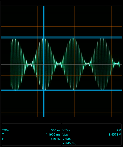
Here’s a 16kHz carrier frequency modulated with an 800Hz signal:
| Amplitude modulation |
|---|
 |
Using that AM generator, I tried out various setups with a Greinacher voltage doubler.
I found out a couple of things in those live experiments:
- The carrier frequency must be much higher than the highest audio frequency.
- The output of the voltage multiplier must have a fairly heavy DC load on it.
I found I could get a cleanly modulated high voltage output if the carrier was more than 1500 times the highest audio frequency. Since the amplifier I was using to drive the multiplier fades out over 17kHz, the highest signal I could use was between 10 and 20 Hz.
The DC load discharges the capacitors in the multiplier on each pulse of the carrier. Without that DC load, you get a pretty steady DC output and no AC really to speak of.
The size of the resistor is somewhat critical. If it’s too large, you get distortion in the output because the capacitors don’t discharge quickly enough to track the audio. You get a kind of “flat bottomed” sine wave. If it’s too small, you start getting the carrier in the output from the multiplier - also not good.
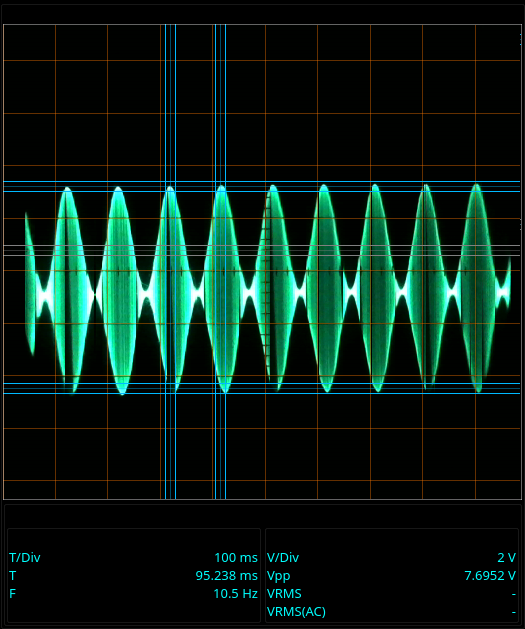
Here are some of the tests I made with the audio AM modulator:
| 16kHz carrier, 10 Hz signal |
|---|
 |
| 16kHz carrier, 10 Hz signal, output loaded with 100k |
|---|
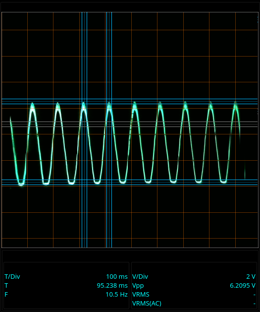 |
That’s too much of a load for the carrier frequency and the capacitors I was using. You can see the 16kHz carrier as that wide trace along the top of the sine wave.
| 16kHz carrier, 10 Hz signal, no load |
|---|
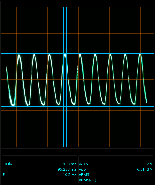 |
That says “no load.” It’s almost true. There’s the DC load of the oscilloscope input. That was enough to collapse the 16kHz carrier and force the output to track the modulating 10Hz signal. It wasn’t enough, though. You can see the distortion on the bottom of the sine wave. There’s a sharp corner, and the bottom of the sine wave doesn’t go far enough down.
The good thing is that the distortion and carrier bleed through can be kept pretty much separate from the audio - if the carrier frequency and the audio frequencies are far enough apart. It works sort of like a simple resistor/capacitor low pass filter. To get good separation between the audio and the carrier with such a simple filter, you need a lot of space between them.
Once I figured out how to make it go, I switched from hardware to a simulator. I don’t have hardware to do high frequency stuff.
I use Qucs rather than the popular LTspice. I actually have LTspice on my computer. It runs just fine on my Linux machine with Wine. I just don’t get a long with LTspice for some reason. I find it difficult to work with. Qucs and I get along better, somehow.
I spent several hours playing with Qucs and pretty much just verifying my first impression that a voltage multiplier could do the job in an electrostatic speaker.
This is my test circuit in Qucs:
| Qucs schematic |
|---|
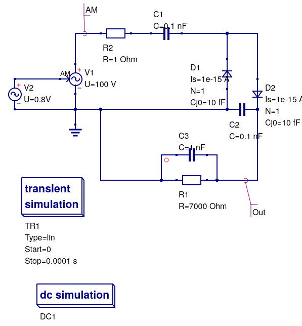 |
C3 represents the electrostatic speaker. R1 is the load resistor. V2 is a simple sine wave generator, and V1 is an AM modulation block. I used R2 to have a look at how much current the circuit draws. From experiments, it seems that V2 “sees” a load of a couple of hundred ohms, while the output is several kiloohms.
This is a simulation I ran using a 10MHz carrier and a 20kHz signal:
| Qucs simulation output - modulated carrier |
|---|
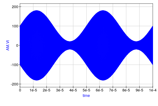 |
| Qucs simulation output - multiplier output |
|---|
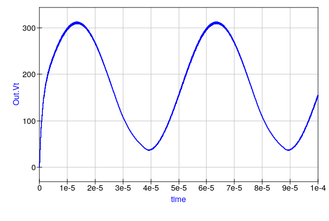 |
That looks fairly low distortion to me. It also seems to be pretty danged flat from 100Hz to 20kHz. I didn’t make snapshots of all the simulations, but I did do simulations over the entire audio range. Once you get the load resistor set to give good results at the high (audio) frequencies, it seems to work just as well at the lower frequencies. Take that, audio transformer.
I’ll have to build a real one and give it a try to see just how well it does (or how poorly.) Simulators are great for when you don’t have the needed parts or can’t do a live test for whatever reason. I just don’t trust them. They are different from reality in too many little ways. I spent a good bit of my time this afternoon twiddling with simulator parameters trying to get it to handle the high frequency carrier and the low frequency (down to 100Hz) audio at the same time without spending all week calculating or breaking off in the middle because of a “jacobian singularity.”
At any rate, I had a fun day and it looks like there might be something to this squirrely idea of mine.
- Do you think this idea is crazy?
- Do you know a better way to drive an electrostatic speaker?
- Do you recognize the source of the phrases in the tag-line of this post?
If you can answer any of those question, drop me a line in the comments below.