Voltage multipliers - Part 7 Impedance of the Cockcroft-Walton voltage multiplier
That got complicated real quick.
Voltage multiplier experiments - Table of Contents
The last time around, I had a look at the impedance of voltage multipliers.
I found that calculating the impedance of a voltage multiplier is much more complicated than I thought. It is so much more complicated that I gave up my attempt to derive a mathematical description of it and went searching the internet.
Eventually, I found this page by Blaze Labs. There’s a lot of hokey free energy bunk on the site, but the notes on the Cockcroft-Walton voltage multiplier seem to be correct.
The Blaze Labs site gives an equation for calculating the output voltage of Cockcroft-Walton multipliers which takes the number of stages into consideration, and which incidentally shows how to calculate the impedance of such a multiplier given the number of stages and the size of the capacitors used.
Here’s the equation:
\[E_{out} = 2nE_{pk} - \frac {I_{load}}{6fC} (4n^3 + 3n^2 - n)\]I extended it to include the diode forward voltage and to correct the impedance calculation (Blaze Labs was using an approximation.)
\[E_{out} = 2nE_{pk} - \frac {I_{load}}{2 \pi fC} (4n^3 + 3n^2 - n) - 2nV_{f}\]What that does is to compute your output voltage from several parameters:
- $E_{pk}$ the peak voltage of the AC input (not the peak to peak voltage, but the simple peak voltage.)
- $I_{load}$ - the load current.
- $f$ - the frequency of the AC input
- $C$ - the capacitance of your individual capacitors (in farads.)
- $n$ - the number of stages in your multiplier.
- $V_{f}$ - the forward voltage of your diodes.
If you search the internet for any of the above text, you’ll probably find a post I wrote on the StackExchange Electrical Engineering site.
The really interesting bit is this:
\[\frac {1}{2 \pi fC} (4n^3 + 3n^2 - n)\]The first section $( \frac {1}{2 \pi fC} )$ is simply the impedance of a capacitor at a given frequency. The second section $(4n^3 + 3n^2 - n)$ is the part I spent several hours trying to derive from circuit measurements before deciding that it would take too many experiments and calculations to nail down.
I need to correct myself at this point. I’ve been talking about impedance, when I should have been discussing reactance. The values look numerically the same, but impedance is the reactance multiplied by $\sqrt{-1}$. That’s called $i$ in the mathematics world, but $j$ in electronics - probably because $I$ is used to denote current.
At any rate, $4n^3 + 3n^2 - n$ is the important thing. That says that the reactance of a voltage multiplier depends heavily on the number of stages.
Given that I got that from a somewhat shady source, I’m going to verify it against some of the multipliers I have here.
Here’s a series of tests with a Cockcroft-Walton multiplier using 10µF capacitors:
| Stages | Calculated Reactance | Measured Reactance | Difference |
|---|---|---|---|
| 1 | 1909 | 4750 | 2840 |
| 2 | 13369 | 16565 | 3196 |
| 3 | 42016 | 45285 | 3268 |
| 4 | 95492 | 98351 | 2858 |
That matches fairly well, except for the 3k difference. I still can’t find the source of that.
Regardless, that pretty much verifies the calculation of the reactance multiplier. So, I’m going let myself be satisfied with that.
Next time around, I’ll summarize all the things you need to design a Cockcroft-Walton half wave rectifier and call it done.
Edited 2020-04-18: I don’t think it’s clear in the text above, but the equation and the measurements are for a half wave Cockcroft-Walton voltage multiplier.
Oh, wait.
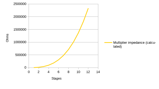
Here’s what the reactance looks like for different numbers of stages:

Exponential, clear as day. It just keeps getting worse the more stages you add.