Transcribing phone calls with Google Live Transcribe - A prototype and a test
Electrically functional, but not quite ready for prime time.
Transcribing phone calls with Google Live Transcribe - Table of Contents
Skip the story and jump straight to a description of a functional transcription adapter.
I had a look at the task a couple of days ago, and made some notes on what needed to be done. I hadn’t intended the sketches to be used - they were concept sketches to show the principle behind the needed circuitry and to explain why a simple lash-up with Y-adapters wouldn’t work.
This evening, I dug out some parts and hunted down some references then drew up a circuit that will work.
This post will go into some more of the theory then show a complete and functional (if ugly) circuit.
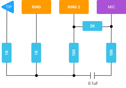
Google has a recommended test circuit for doing audio tests on Android using a single phone. That’s called a “loopback” circuit because it takes the eaphone output and makes a loop back into the microphone input of the same phone.
Here’s Google’s test circuit:
| Google’s loopback adapter |
|---|
 |
I adapted that to be used to connect the earphone output of one phone to the microphone input of a second phone.
Here’s the circuit I settled on:
| Transcription adapter circuit |
|---|
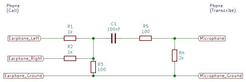 |
| Edit 2021-05-04 Note: This circuit works, but is not optimal. I will post a better version soon. |
I’m sure you can see the similarity with the example circuit I drew in my last post.
The attenuation is the same in both circuits - 10 to 1. That is, the microphone input level is about 1/10 the earphone level. They use different values, but with the same ratio (Google used 1k to 100 ohms, I used 10k to 1k.) For the real circuit, I went with Google’s values.
Referring to my diagram, here’s what the individual parts all do:
- R1 and R2 mix the audio from the earphones. That way, you are guaranteed to get the voice from the phone call.
- R3 together with R1 and R2 forms an attenuator. The junction of R1, R2, and R3 has the sum of “Earphone_Left” and “Earphone_Right” divided by 10.
- C1 is a coupling capacitor. Without it, the “transcribe” phone would “see” a button press (caused by R3,) and do something other than simply switch to the external microphone input. (See Google’s “3.5 mm Headset: Accessory Specification” for details of the audio accessory buttons.) C1 prevents the flow of DC from the microphone input while allowing the audio to pass.
- R4 is there to signal the “transcribe” phone that an external microphone is connected.
- R5 is presumably there to reduce short circuit current through the capacitor.
Describing it all that way reminded me that C1 and R4 form a high pass filter. The cutoff is around 790Hz. That’s rather high and is probably removing too much of the lower frequencies from the audio. (Speech is usually considered to be between 300Hz and 3kHz.) I’d recommend using at least 330nF (cutoff around 200Hz.) I’ll change the circuit diagram when I draw up the final plans.
From that diagram, I built an adapter using a 4 pin headphone plug and an old headset.
Here’s the assembly of the test adapter:
- Plug
| Four pin headset plug |
|---|
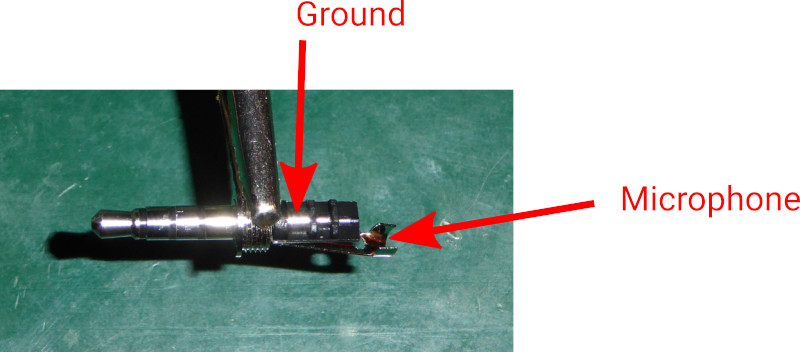 |
| Note the location of “Ground” and “Microphone” - make sure to connect them properly. Old three pin headsets had the ground connected to the shell. The four pin headsets have the microphone connected to the shell. |
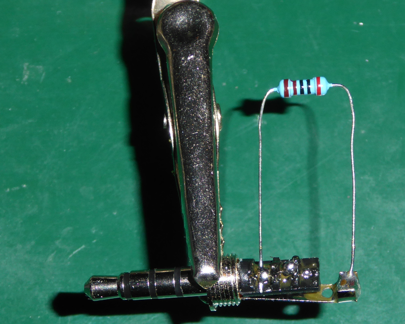
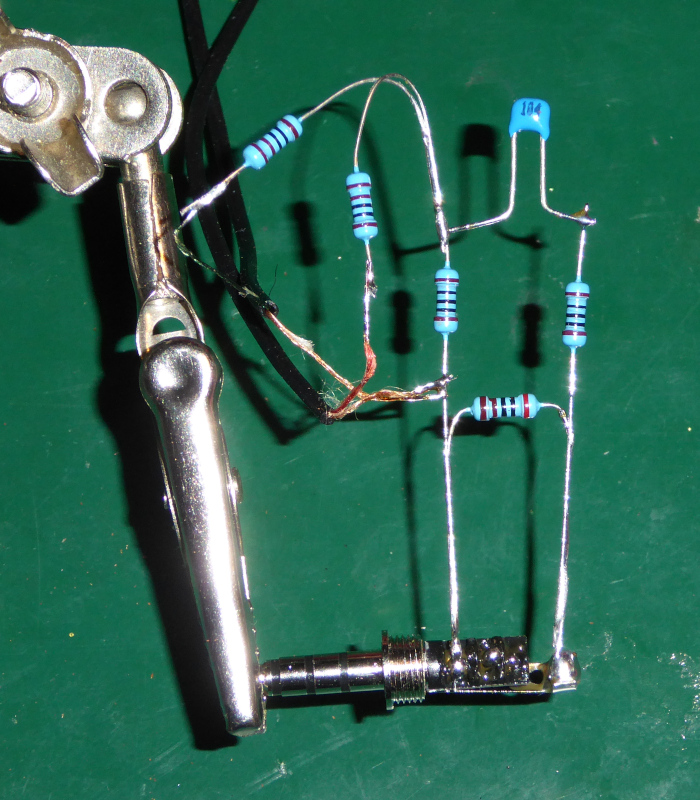
- Connect R4
| R4 - external microphone select 2k |
|---|
 |
- Connect R3
| R3 - attenuator 100 ohms |
|---|
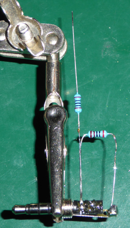 |
- Connect R5
| R5 - short circuit protection 100 ohm |
|---|
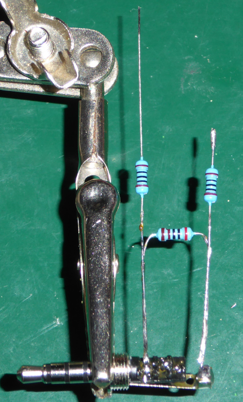 |
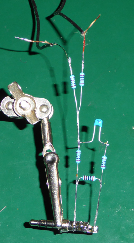
- Assemble summing circuit
| R1 and R2 - summing circuit two 1k resistors |
|---|
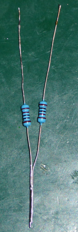 |
- Attach summing circuit and C1
| C1 and summing circuit - AC coupling 100nF |
|---|
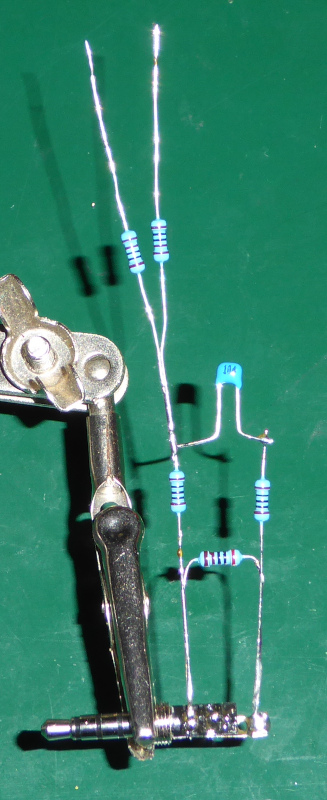 |
- Connect earphone left and right
I cut the earphones off of an old Android headset and connected the wires to the adapter.
| Earphone connection |
|---|
 |
- Connect earphone ground
| Earphone ground connection |
|---|
 |
- Completed assembly
Note that I connected the earphones to the adapter. You can hear and speak using the headset while the “transcribe” phone can “hear” the voice from the call.
| Complete adapter |
|---|
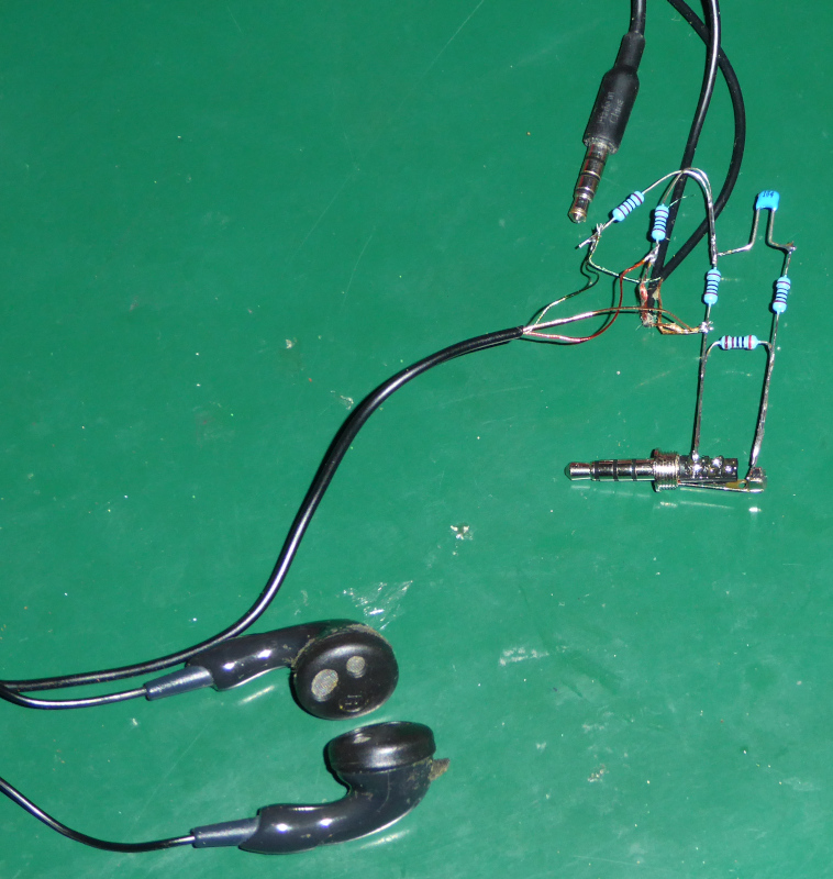 |
That’s it electrically.
I plugged the adapter into a couple of phones (“call” is the gold phone, “transcribe” is the black phone) and called the “call” phone from a (cordless “Siemens”) landline telephone.
Here’s the result of that phone call:
| Successful transcription of a phone call |
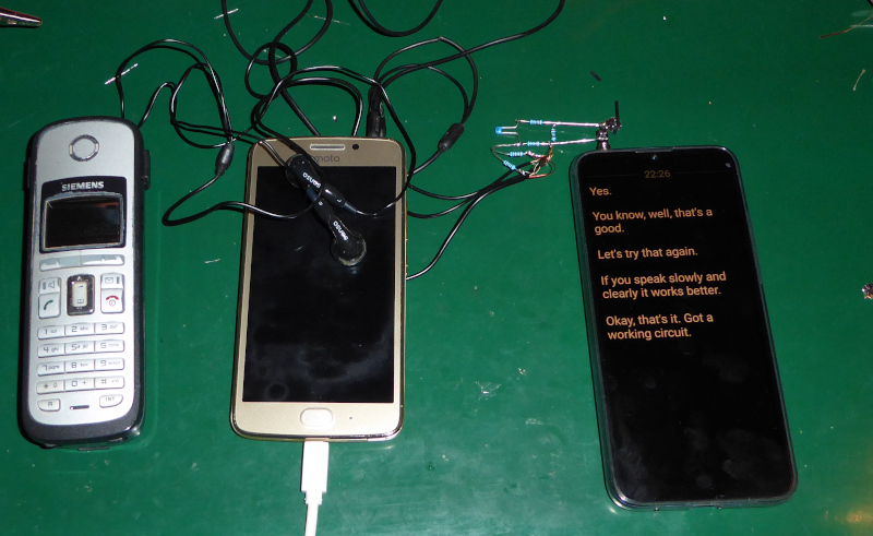 |
Google “Live Transcribe” prefers that you speak slowly and clearly. The “transcribe” phone transcribes just as well with the adapter as it does with the normal, built in microphone.
With the electrical parts all cleared up, the question now is “What’s the best way to build these?”
There’s a couple of ways to build them, and I’m not sure which is easiest and cheapest. I suspect “cheapest” will depend on what is readily available to the folks who need the adapters. I’ll have to check with the person who started this to see which way is best.
In my next post, I’ll describe a couple of ways that this could be built. The problems from here on out are all mechanical and depend on what parts are available.
Transcribing phone calls with Google Live Transcribe - Table of Contents