Transcribing phone calls with Google Live Transcribe - An adapter made from common parts
Not the cheapest way but certainly a reproducible way.
Transcribing phone calls with Google Live Transcribe - Table of Contents
I’ve been trying to think of the most easily reproducible way to build a transcription adapter the last couple of days.
The biggest problem is that I don’t know what is available to the people who might want to make one or have one made.
The plugs and jacks can be ordered, or are sometimes available in local shops though not always, and deliveries can be uncertain what with the lockdowns and such going on.
I finally decided that whatever else may or may not be available, people who need an adapter have access to headsets for their phones.
The most certain way to make an adapter is to build it out of two headsets. Most nearly everyone has a headset available, and often an old one from a no longer used phone as well. Even if someone doesn’t have a couple of old headsets at hand, they can often be bought locally.
The electrical components are also common parts - the resistors and capacitor are all standard values that will be in stock nearly anywhere that electronics parts are sold.
I have parts on order to build an adapter from plugs, sockets, and cables, but it will take a few days for them to arrive.
In the mean time, here’s how you can build your own transcription adapter:
Parts
You will need the following parts to construct your transcription adapter:
| Component type | Component designator(s) | Value | Quantity |
|---|---|---|---|
| Resistor | R1, R2 | 1k | 2 |
| Resistor | R3, R5 | 100 | 2 |
| Resistor | R4 | 2k | 1 |
| Electrolytic capacitor | C1 | 4.7µF | 1 |
| Android phone headset | 2 | ||
| Small insulated box | 1 |
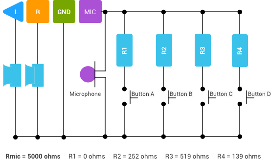
The component designators refer to the following diagram:
| Adapter circuit diagram |
|---|
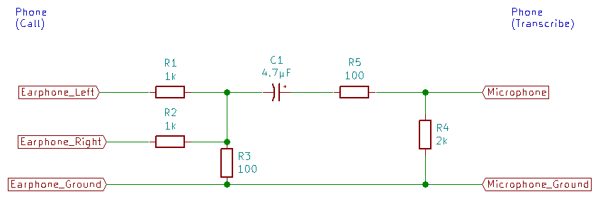 |
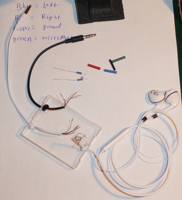
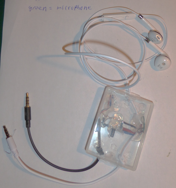
Here are the parts I used to build an adapter:
| Adapter parts |
|---|
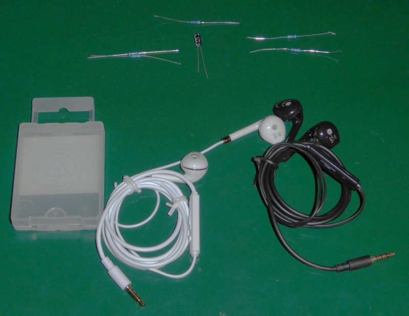 |
You will also need some insulating tape or heat shrink tubing and some glue or epoxy (I used a hot melt glue gun.)
Tools
If you are planning to make your own adapter, I would expect you to already have tools for soldering.
If this is to be your first project using a soldering iron, then I suggest you refer to this list of tools, then work your way through the “HowTo: Solder by hand” series to at least the “HowTo: Solder by hand - Solder wires together” entry.
I will be adding a section to the HowTo: Solder by hand series describing how to solder the fine stranded wire inside the headset cables.
2021-05-15: I’ve added a post to the HowTo: Solder by hand series. Take a look here for instructions on replacing an Android headset plug. Skip straight to this section to see how to tin the fine wires of a headset cable.
You will also need a multimeter - specifically, a meter that can measure resistance.
Preparation
You’ll have to cut the plugs off of both of the headsets in order to build an adapter. Leave about 10 cm (4 inches) of cable on the plug.
| Cut cable |
|---|
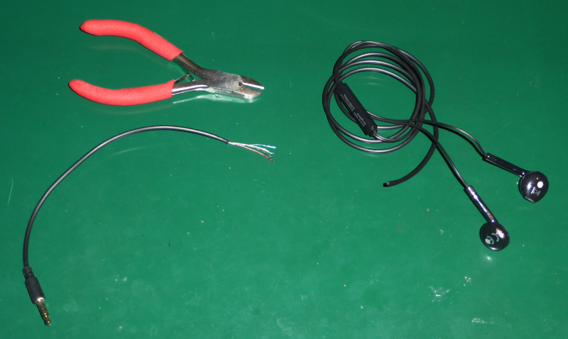 |
Remove the outer insulation from both ends of the cut cable. Be careful - it is very easy to cut into the wires inside.
Tin the ends of the individual wires. Do them all immediately after stripping the cable. The strands of the wires will come untwisted if you don’t tin them. Once they are untwisted it is very difficult to get them back together.
There is often a thread (non-conducting white string) down the middle of the wires. Leave it there, and tin the stranded wires. The thread will burn (or melt) out of the way. I will explain how to tin the wires in a separate post in the HowTo: Solder by hand series.
| Stripped cable |
|---|
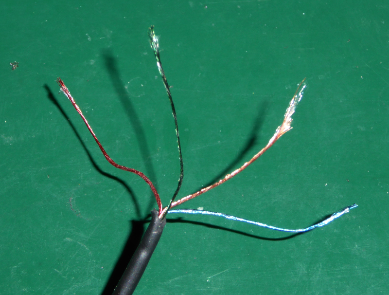 |
There are four wires inside the cable. One wire goes to each of the metal parts of the plug. Since there is no color coded standard for the wires in the headset cable, you will have to map out the colors yourself. If you have two different headsets then you will have to map out both sets of wires.
| Mapping out the cable and plug |
|---|
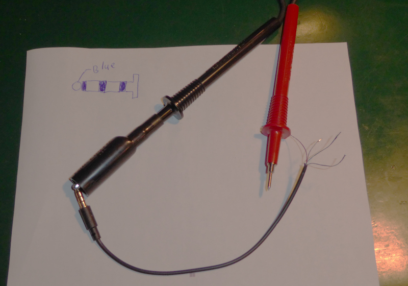 |
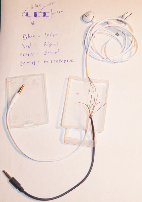
I made a sketch of the plug, then used my multimeter to measure between each metal part and the ends of the wires to find the connections.
The final map looks like this:
| Mapped wire colors |
|---|
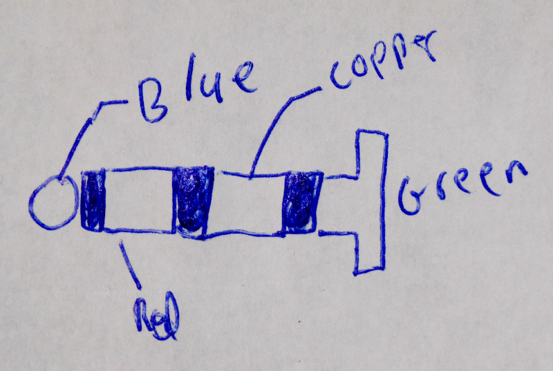 |
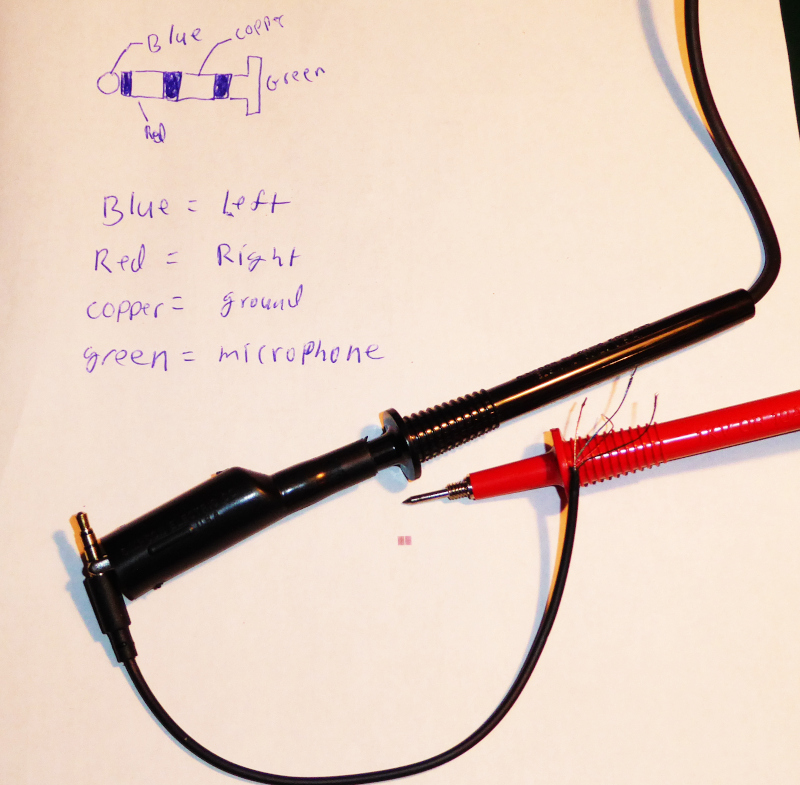
Comparing the plug pins to the Google headset specifications, I made a table that maps the colors to the functions.
| Google headset connections |
|---|
 |
| Wire colors to functions map |
|---|
 |
Check your cables and plugs, and make tables that map the wires of your headsets to the needed functions. You’ll need those tables to properly connect your headsets to make the adapter. You’ll be referring to them all through the following construction steps.
Construction
Take your box or other container and arrange it with the prepared cables. You have to decide how things should fit together.
I used a small plastic box from a package of screws. It is large enough to hold all the parts, but small enough to stay out of the way.
| Choosing the circuit layout |
|---|
 |
I had you cut both cables, but you’ll be soldering one of them back together. In my adapter, that’s the headset with the white insulation. I have its plug going into the box, and the rest of the headset coming out of the other end of the box. I have the black plug coming out of the box at the same end as the white plug. The black plug goes to the phone with Live Transcribe running.
With both plugs at one end, I can put both phones side by side. Maybe your two phones have the sockets at different ends of the phone so that it would make more sense to have the plugs at opposite ends of the box. Lay things out, and decide what will work best for you and your phones.
Once you have decided how things will work best for you, drill holes in the box for the cables. You want them just barely big enough for the cables to pass through them.
Pull the cables into the box. You want about three or four centimeters inside the box.
| Drill holes in the box |
|---|
 |
Tie knots in the cables so that they cannot pull out. Arrange the knots and the cables so that the cables all meet in the middle of the box with a little slack to work with.
| Knotted cables |
|---|
 |
Connect the headphone “Left” and “Right” wires together (“Left” to “Left and “Right” to “Right,”) then connect a 1k resistor to each of them (R1 and R2.)
| Connect “Left” and “Right” |
|---|
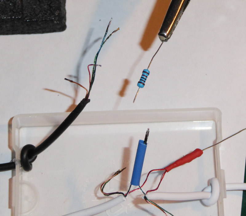 |
The picture shows the “Left” wires connected and about to be soldered to the 1k resistor. The “Right” wires are already connected and attached to the 1k resistor.
I insulated the connections with color coded heat shrink tubing. You can use electrical tape or heat shrink tubing, it doesn’t matter - but the connections need to be insulated. They will be close together and could cause a short circuit if not insulated.
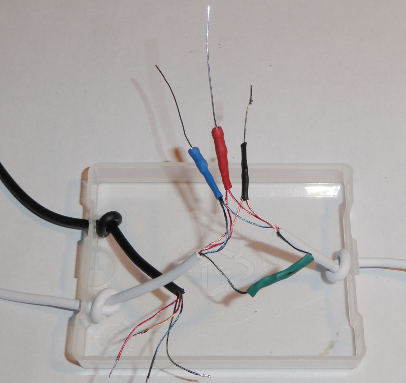
Solder the ground wire and the microphone wire of the headset together. Add a piece of cut off wire from one of the resistors to the junction of the ground wires.
Again, insulate the connections to prevent short circuits.
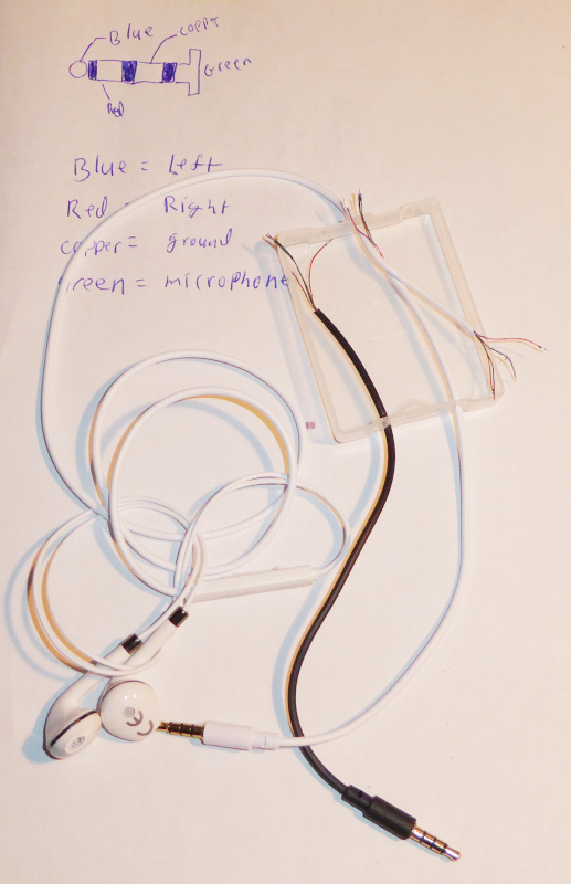
| Headset reconnected |
|---|
 |
At this point, the headset should be functional again. Make sure the free ends of the wires aren’t touching, then connect it to your phone and make a call with it to be sure that the microphone and both earphones work. If it doesn’t work, check and correct all connections. Do not continue with the construction until the headset works properly again.
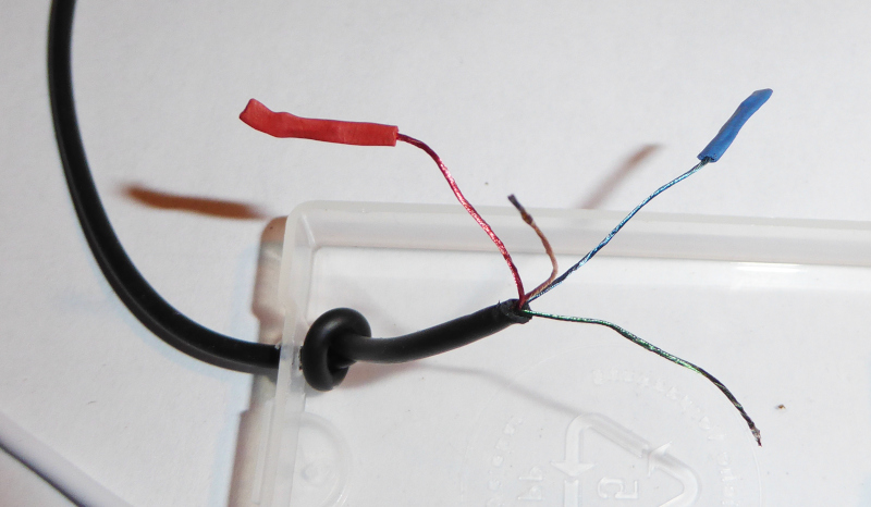
Insulate the wires for the “Left” and “Right” connections on the second plug. They aren’t needed, but could cause a short circuit if not insulated.
| Insulate “Left” and “Right” |
|---|
 |
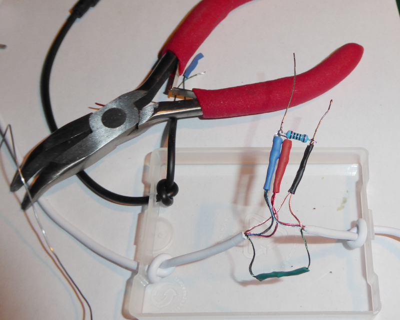
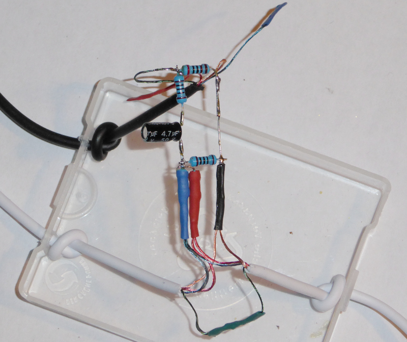
Assemble the attenuator. Connect the ends of the resistors on “Left” and “Right” (the free ends of R1 and R2) from the headset together. Connect those two resistors to a 100 ohm resistor (R3.) Connect R3 to ground.
| Assemble the attenuator |
|---|
 |
Connect the coupling capacitor (C1) to R3.
| Coupling capacitor |
|---|
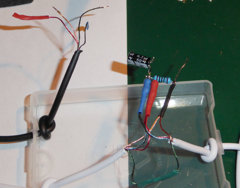 |
Pay attention to the negative stripe on the capacitor. The pin indicated by the negative stripe goes towards the resistors (towards the earphones.)
Connect R5 to C1.
| Connect R5 |
|---|
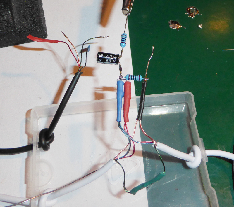 |
Connect the external microphone select resistor (R4, 2k) between R5 and ground.
| Connect the external microphone select (R4) |
|---|
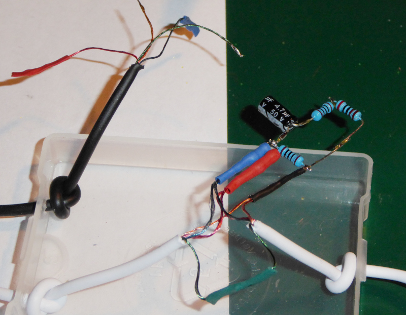 |
Connect the “transcribe” plug to the attenator.
The microphone wire goes to the junction of R4 and R5, while the ground wire goes to the other end of R4 (that’s the ground of the other headset.)
| Connect the “transcribe” output |
|---|
 |
Everything thing is now electrically complete. Plug it into two phones, and make a phone call. The headset should work correctly, and the “transcribe” phone should transcribe the text from the call. It is only intended to transcribe what comes in through the headphones. It will not transcribe what you say into the microphone of the headset.
Try it out, make sure it all works. Do not continue until it all works properly.
| Transcription test |
|---|
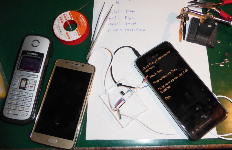 |
When it all works, glue the electrical parts of the adapter in place inside the box, then close the box. You might want to glue it shut so that it doesn’t pop open on accident while you are using it.
| All done |
|---|
 |
That’s a transcription adapter made from two headsets. It may not be the cheapest way to do it, but it is almost certain that all of the needed parts will be available anywhere in the world where people use Android phones.
I’ll write up how to build an adapter using plugs and sockets when the parts I’ve ordered get here.
Transcribing phone calls with Google Live Transcribe - Table of Contents