Transcribing phone calls with Google Live Transcribe - A properly functioning loop-back adapter
A CTIA four pole plug and a few spare parts.
Transcribing phone calls with Google Live Transcribe - Table of Contents
Besides transcribing phone calls, you’d think Google Live Transcribe could be used to transcribe podcasts and similar things - but, again, Live Transcribe can’t transcribe the audio from playback on the same phone it is running on.
The answer to that is a loop-back adapter that feeds the earphone audio from one phone back into that same phone’s microphone input.
That’s pretty much just the circuit that this all started with - the loop-back adapter that Google recommends:
| Google’s loop-back adapter |
|---|
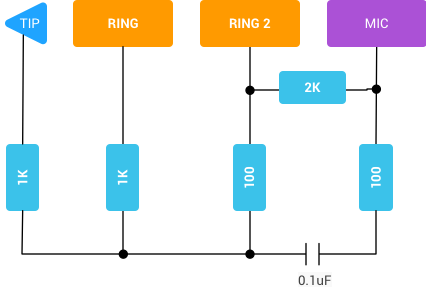 |
| Do NOT use this circuit. It is very far from optimal. |
If you’ve been following this series of blog posts, then you know that I tested Google’s circuit and then improved it for a better frequency response.
| Adapter circuit |
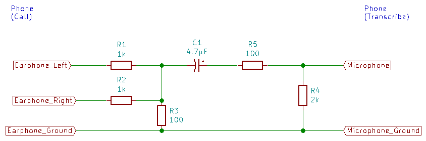 |
| Use this circuit. It works well. |
The only difference is the value of the capacitor. Google’s recommended circuit cuts low frequencies something awful.
My circuit shows the earphone and microphone connected to separate phones, but it can also be built to connect the output of one phone to the same phone’s input - it can be built as a loop-back adapter just like Google’s circuit.
I built one and tried it out. It works just fine.
Here’s how I put mine together.
You’ll need the following parts:
| Component type | Component designator(s) | Value | Quantity |
|---|---|---|---|
| Resistor | R1, R2 | 1k | 2 |
| Resistor | R3, R5 | 100 | 2 |
| Resistor | R4 | 2k | 1 |
| Electrolytic capacitor | C1 | 4.7µF | 1 |
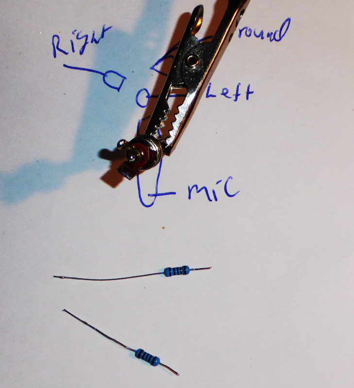
| 4 pole CTIA (TRRS) plug | 1 |
| Parts |
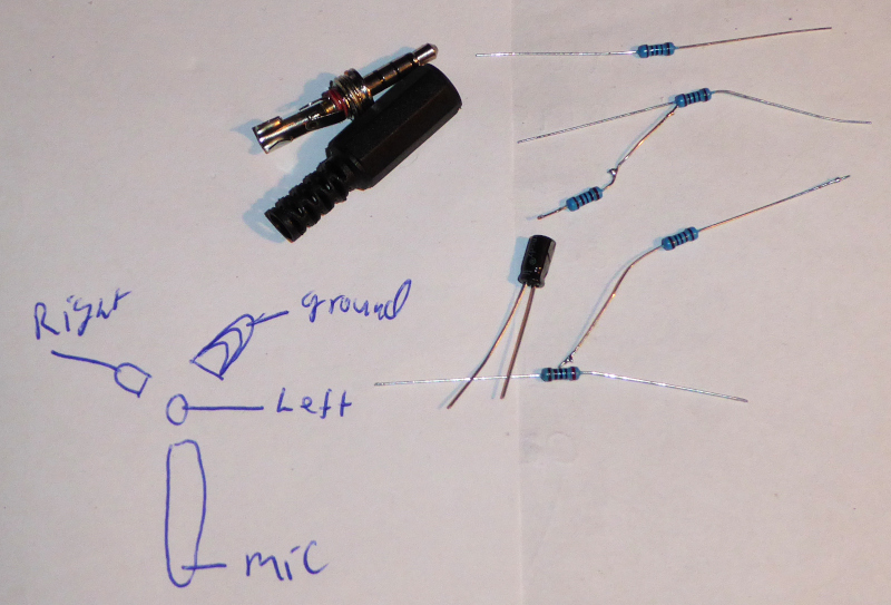 |
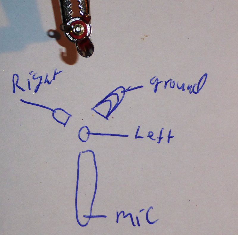
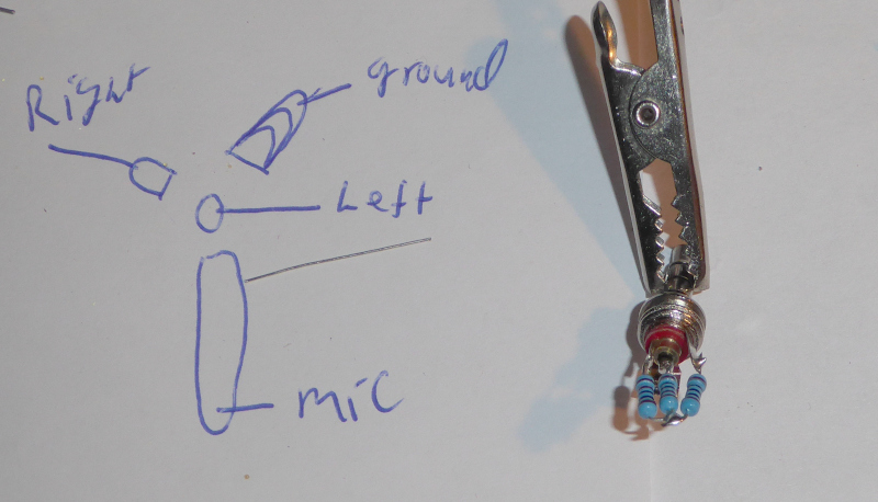
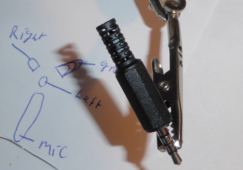
You’ll also need to figure out which parts of the plug go to which solder tabs. I reused a sketch I made last week for the plugs I have. Refer to the Howto:Solder by hand - Repair an Android headset post for instructions on finding the connections on your plug.
| Solder tab connections |
 |
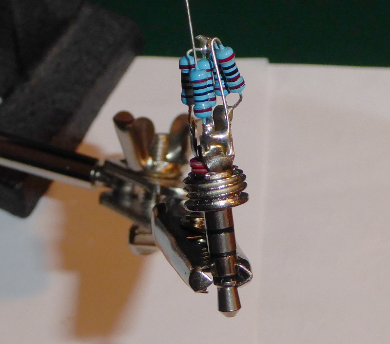
First connect R1 and R2 (1k each) to the earphone solder tabs.
| Connect R1 and R2 |
|---|
 |
| Note that I have shortened the “microphone” solder tab. There is barely enough space inside the connector shell for the needed parts. |
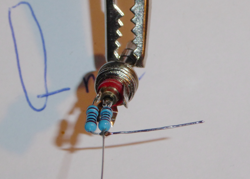 |
| Connect the free ends together while you are at it. |
Connect the junction of R1 and R2 to ground via R3 (100 ohms) to form the attenuator.
| Connect R3 to make the attenuator |
 |
Connect R4 (2k) between the microphone and ground so that the phone will use the external (headset) microphone input.
| Connect R4 |
|---|
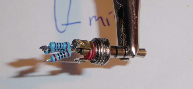 |
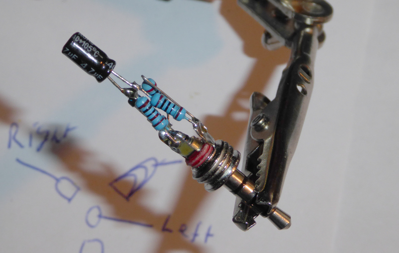
Connect R5 (100 ohms) in series with the microphone connection.
| Connect R5 |
|---|
 |
Connect C1 between the attenuator output and R5 (the microphone series resistor.)
| Connect C1 |
|---|
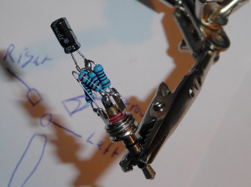 |
 |
| Make sure that the negative side (with the “-“ stripe) goes towards R1 and R2 while the positive side goes to R5. |
It should work now. Plug it into your phone and make sure that Live Transcribe can properly transcribe from playback on the phone.
If it doesn’t work, check for short circuits and make sure you’ve assembled it correctly. Remember that you have to sketch the TRRS connections and the solder tabs for your plug. They may not be the same as on my plug.
Once it works, you can screw the shell onto the plug.
| Done |
|---|
 |
| You can see the capacitor through the slits in the shell. |
There you have it: a functional loop-back adapter that you can use with Live Transcribe.
| Final test |
|---|
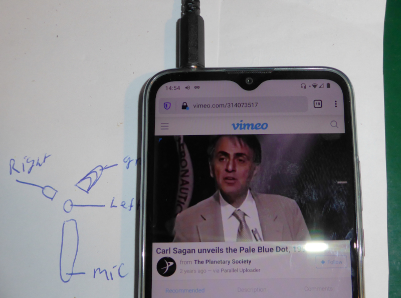 |
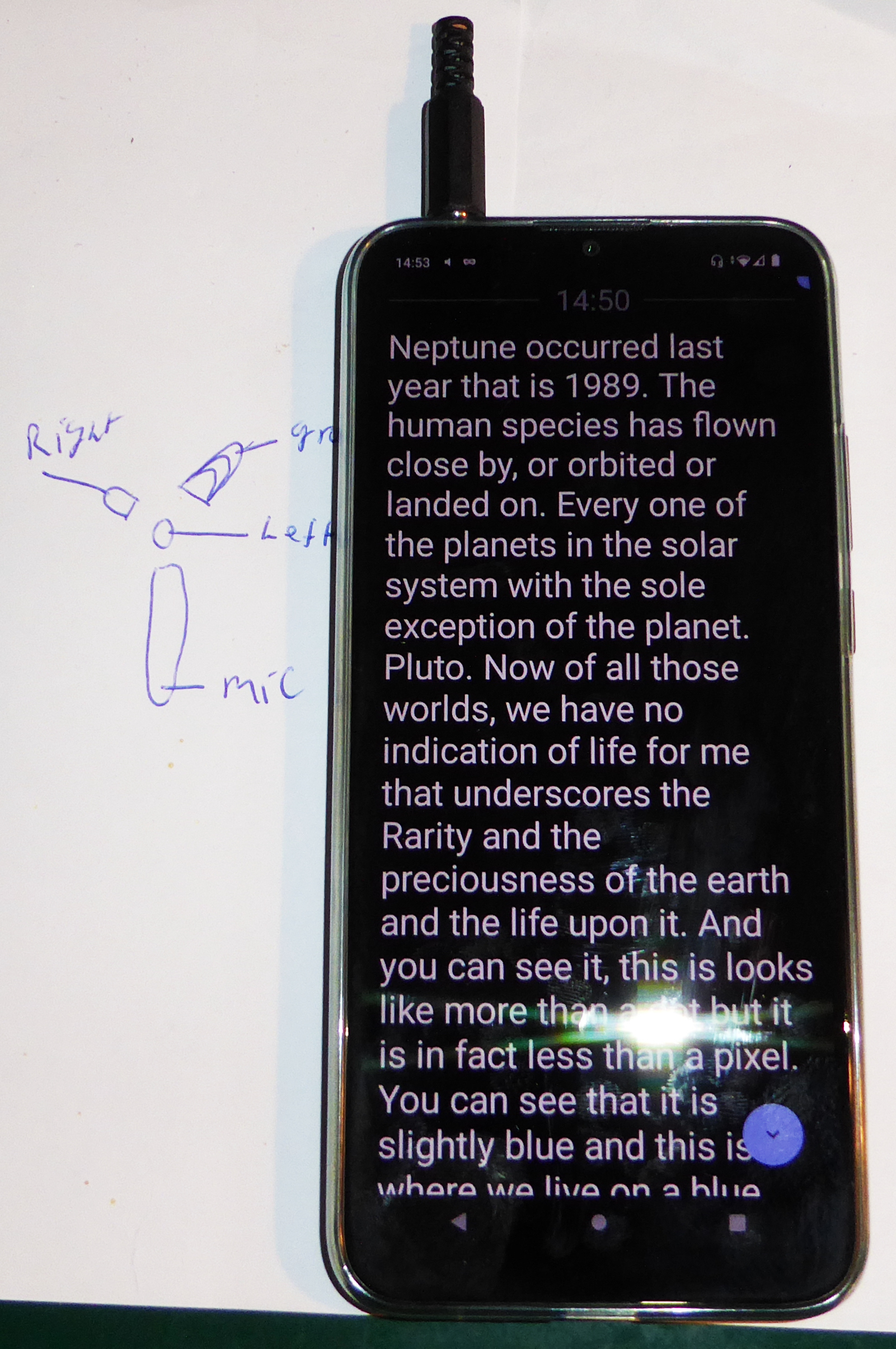 |
| That’s Live Transcribe transcribing Carl Sagan’s Pale Blue Dot speech. |
| Playback and transcription on one phone. |
Transcribing phone calls with Google Live Transcribe - Table of Contents