Oscilloscope camera adapter design considerations
Hardware for the software.
My Telequipment D43 projects - Table of Contents
A couple of months ago, I wrote a program to capture images of my oscilloscope.
I used a webcam that I bought for the purpose, and built an adapter to mount the camera on my scope. I’m getting ready to build a new one, because the webcam I used the first time around kind of sucks, and I made the mount too short for the camera to focus properly.
This is what the old camera mount looks like:
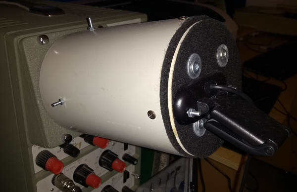
You’ll notice that the screen of the scope is totally enclosed, and that there’s a lot of black stuff on it.
The camera mount is supposed to be light tight. It isn’t really, but it does block out a lot of the light in the room.
I tried to make it light tight for two reasons:
- Fast events on an analog oscilloscope aren’t very bright.
- I want the grid and the face of the screen to be dark.
That first point is pretty standard: any photographic camera you will find for an old oscilloscope is light tight so that you can use a wide open aperture on the camera to capture as much as possible of the light from the trace. This needed to capture single shot events at high speed.
The second point is a bit weird, though. While I was writing the software, I found that it is next to trivial to digitize the trace - as long as a couple of conditions are met.
The first condition is that there’s only one trace on screen. The second is that there be no other details in the way. The first is easy enough to arrange, even on a dual trace scope like my D43. The second requires that you turn off the back light and make sure there are no reflections. If you do that, you get a nice, matte black image from which you can easily extract the (relatively) bright, colored trace.
My Digital D43 program generates the grid itself once you’ve got it all calibrated, so it’s not a problem that you can’t see the original grid.
That’s a couple of requirements for the mount already: proper length for focus, and light tight.
Another thing that has to be considered is how the adapter is to be held onto the scope.
In that first adapter, I have a couple of rings of plastic inside the barrel. The flange of the oscilloscope hood fits between the rings, and there’s layers of felt in between to cushion things and block the light. The adapter is actually held in place by the friction between the oscilloscope hood and the felt lining.
That ring system works fairly well - it is easy to attach and remove, and I can rotate the camera to get the trace parallel to the horizontal lines of the camera pixels.
It has one big disadvantage, though. The innermost ring blocks some of the screen of the scope, cutting off small areas at the four corners of the grid.
The cut off corners look like this:
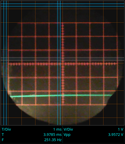
(You can also see how fuzzy the focus is. The original grid is visible, and horribly out of focus.)
That gives me two more requirements for the new adapter: it needs to be adjustable, and the mounting must not block the camera’s view of the screen.
The old adapter is already adjustable. The camera itself is mounted on a plate on the back of the adapter, and “sees” the screen through a smaller hole in the back of the tube. The camera plate is mounted so that by loosening the four screws on the back plate, I can push the camera plate up and down or left and right to center the camera in front of the screen.
I’ll be keeping that feature in the new adapter.
A final word on the length, and then I’ll summarize all of this.
The resolution of the camera is fixed. Its focal distance is fixed. To get the highest resolution image of the trace, you want the camera as close to the screen as possible. To get the sharpest image of the trace, the camera has to be at least as far from the screen as its focal distance.
Before making the tube for the next adapter, I’ll measure the focal distance of the new camera (which I also did for the first one) and make sure the tube is long enough (I flubbed that the last time around - I cut one end of the tube crooked, and by the time I got the tube ends parallel again I’d lost over an inch of length on it.)
Summary of the requirements:
- Light tight (loads of black felt)
- Proper length (measure the focal distance, tube must be that long but no longer.)
- Adjustable - horizontally, vertically, and rotation.
- No protruding parts inside the tube.
It’ll be a couple of days until I can start making parts. I’ve got ideas ready, and I’ll sketch the parts out and post them with the finished camera mount in a few days.