Diodes and capacitors and volts - Oh, my!
Let’s talk about voltage multipliers.
Voltage multiplier experiments - Table of Contents
For various reasons (including two explosions in the high voltage power supply of my old oscilloscope,) I’ve had to get familiar with voltage doublers - or rather, voltage multipliers.
A voltage multiplier is a simple construction of diodes and capacitors that can be used to turn a relatively low AC voltage into a higher DC voltage.
If you are interested in the history of the things, and the various types, then check out the Wikipedia “Voltage Doubler” site, or the Wikipedia “Voltage Multiplier” site. I’m not going to go into all of that.
What I want to do is to is to put down some practical experience with them, and some examples of what you can expect from them.
Towards that end, I’m going to write a few blog posts. There’s just too much information to comfortably fit in a single post.
I’ll start with an introduction to the parts and tools I’ll be using. The next post will start with a description of a simple rectifier circuit and the simplest voltage doubler.
The cast of characters:
Here are the parts I’m going to use:
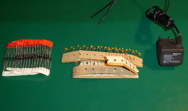
A big pile of diodes, a big pile of two different values of capacitors, and a transformer to provide a safe source of AC.
These are the main tools I’ll be using:
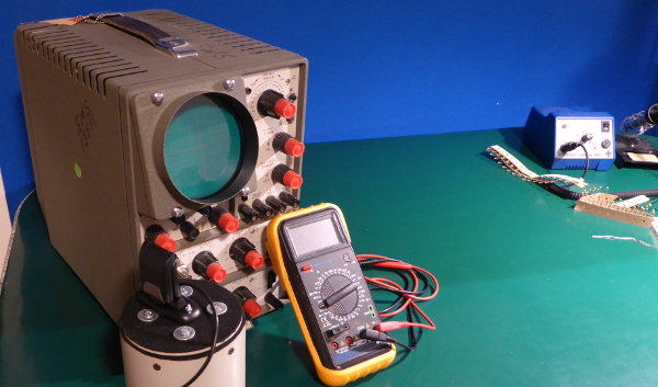
That’s my D43 oscilloscope and its camera along with my multimeter. Nothing fancy. In the background you can see my hardware store soldering iron. Also not fancy, but workable.
Getting personal:
Let’s get a little more intimate with the parts. I’m going to use them to build various rectifier and multiplier circuits, so I need to be familiar with their characteristics.
Since I bought them at Conrad Electronics, they didn’t come with datasheets. No matter. These are common parts, so we’ll just refer to common datasheets and pretend they’re the real thing.
First, the transformer. I don’t even have a pretend datasheet for this thing. It’s a bit of junk that’s been banging around the house in need of a job for the last twenty years. It is, however, clearly marked with voltage and current ratings.
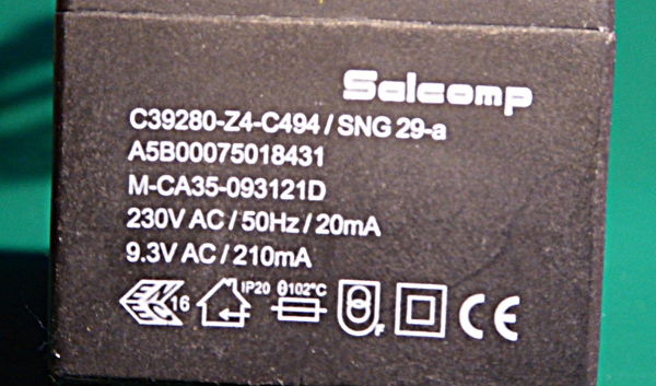
It is a small wall wart rated for 9.3VAC and 210mA output. These are important bits of information. They let me pick the diodes and capacitors.
Given the way voltage doublers and multipliers work, you only need parts good for the twice the input voltage. The 9.3VAC lets me approximate the maximum voltage to be expected.
The 210mA is also important. From that, I can decide what current carrying capacity my parts need.
These are the diodes I’ll be using:
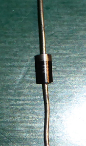
I bought a bunch of 1N4001 diodes. They are rated for 50V DC, and 1A of current. From earlier experiments, I know that I’ll get around 40V out of a doubler operated from my little transformer. 50V is therefore adequate as a voltage rating. Since the tranformer can’t deliver more than a couple of hundred mA, the current rating on the diodes is fine.
Strictly speaking, 9.3VAC works out to 26 V peak to peak, which when doubled would exceed the rating of these diodes. I should have bought 1N4002 diodes (rated for 100VDC) to be safe, but I didn’t want to push my luck with Conrad - it was pure luck they had enough 1N4001 diodes on hand. But, I know what this transformer can deliver - and under load it is low enough that I can use the 1N4001 safely.
Here’s a better view of the capacitors:
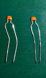
Hmmm. The photo isn’t that legible. Well, they are marked 103 (for 10nF) and 104 (100nF.) Both are rated for 50VDC - if the guy at the counter at Conrad can be trusted. I’m going to make some multipliers with 10nF, and some with 100nF in order to demonstrate the effects the capacitance has on performance.
That’s enough introduction.
The next post will get into the circuitry.
(PS: If you live in the Mainz, Germany area and intended to buy 1N4001 diodes or 100nF capacitors from Conrad Electronics in the next couple of days, I’m sorry. They are all out. I have all of them in my work room.)