Voltage multipliers - Part 4 More on the Cockcroft-Walton voltage multiplier
Why do something that looks like a problem?
Voltage multiplier experiments - Table of Contents
The last time around, I looked at the Cockcroft-Walton voltage multiplier.
Though it isn’t as simple as the doublers, it is extendable and easily predictable. One stage gets you half the peak to peak AC as DC, and you just add stages to get more voltage.
It also turns out to have a small problem - the output voltage drops if the load is too heavy. I implied that the very design of the Cockcroft-Walton multiplier was responsible for that drop. I’m going to explain why that is, and why you would build it the way it is even though you have to accept the voltage drop under load.
Here’s the circuit I’ve been using:
| Three stage Cockcroft-Walton multiplier |
|---|
 |
If you look at it closely, you’ll realize that there’s a row of capacitors across the top and bottom connected in series.
Let’s remove the diodes. I’m just going to brutally paint them over:
| Three stage non-multiplier |
|---|
 |
Those capacitors are clearly in series. In series circuits, resistances (and impedances) add. If we close the loop with a resistor (or wire,) we’ll find that we have four capacitors in series. That’s four times the impedance of a single capacitor.
Well, how much is the impedance of a capacitor?
That depends on the frequency of the AC trying to pass, and the capacitance of the capacitor.
I’m in Germany, so we have a power line frequency of 50 Hz.
I’m using 100nF capacitors.
The impedance Z of a capacitor is found by the formula Z = 1 / (2 * Pi * f * C) where Pi is the well known constant, f is the frequency in Hertz, and C is the capacitance in farads.
For my parts and line frequency, that comes out to 31.8k Ohms. With four of them in series, that’s 127.2k Ohms. Any load that approaches that impedance will noticeably lower the output voltage. I’m going to skip explaining voltage dividers.
Sufficient to say, a load of 123k Ohms on the voltage multiplier I’m using would lower the voltage to half that of an unloaded voltage multiplier.
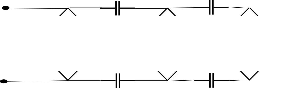
We could reduce the impedance by connecting all the stages in parallel to the AC input.
| Parallel Cockcroft-Walton stages |
|---|
 |
If I do just that, the voltage for the three stage multiplier looks like this:
| Parallel Cockcroft-Walton stages |
|---|
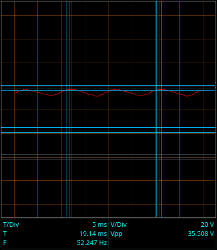 |
36 Volts. That’s much better than the series stages. Why are Cockcroft-Walton multipliers made in series, then?
I’ll show you.
Let’s look at the voltage on the capacitors feeding each stage.
| Capacitor | DC Voltage |
|---|---|
| 1 | 15V |
| 2 | 26V |
| 3 | 14.4V |
| 4 | 30.3V |
Capacitors 2 and 4 both have the highest voltage across them. As you add stages, the voltage across the capacitors feeding the higher stages goes up by the stage voltage. So if the total voltage is expressed as (number of stages) * ( stage voltage ), the voltage across the feed capacitors can be expressed as (number of stages - 1) * ( stage voltage )
If you are building high voltage output multipliers, the required voltage rating on your stage feed capacitors can get really high.
Now let’s compare that to a standard Cockcroft-Walton multiplier.
| Capacitor | DC Voltage |
|---|---|
| 1 | 16.3V |
| 2 | 16.3V |
| 3 | 16.2V |
| 4 | 16.3V |
The upper stage capacitors are never exposed to more than the stage voltage.
There at last lies the reason why Cockcroft-Walton voltage multipliers are built in series.
If you build high voltage Cockcroft-Walton multipliers, all of your parts must be rated for the stage voltage. That’s sufficient.
If you were to feed the stages in parallel to reduce the impedance, then you would need capacitors rated for a very large part of the final output voltage.
If you are playing with piddly stuff like I am, then it doesn’t matter. It would take a five stage multiplier to exceed the voltage ratings on the capacitors I’m using. The output voltage would be about 70V to 75V, and the capacitors for the final stage would be exposed to 60V. In my case, I bebop over to Conrad (or order parts from a better supplier) and get capacitors rated for 150V, and all is good. If I were trying to generate a few million volts for a particle accelerator then it would be much more difficult to get higher rated parts.
Summary:
- You use a standard Cockcroft-Walton multiplier despite the problem with loading because it lets you use lower voltage ratings on your parts.
- You could connect all your stages in parallel if your final output voltage is low enough that you can get properly rated parts.
Now that I’ve had a look at all the various types of voltage doubler and voltage multipliers, I’m going to round them all up in the next installment and show you that they are all the same - and while I’m at it, you’ll see why I started the discussion of Cockcroft-Walton voltage multipliers with the full-wave version.