Voltage multipliers - Part 3 The Cockcroft-Walton voltage multiplier
The big league.
Voltage multiplier experiments - Table of Contents
I’ve gone into the Villard and the Greinacher voltage doublers in the two previous installments of this series.
If you need to double the DC you get from AC, then those two will do the job.
If you need more than that, then you need to look at voltage multipliers.
I’m going to start with the full wave implementation of the Cockcroft-Walton voltage multiplier.
The usual progression is from the half-wave Cockcroft-Walton to the full-wave version. I’m going the other way around because I personally have an easier time understanding the full-wave version - and from there it is easier to grasp the half-wave version.
For this diagram, I’m also going to to switch from KiCAD to Inkscape.
KiCAD is a great tool for drawing circuit diagrams and making printed circuit boards. I use it for all my hobby stuff.
KiCAD is just not so great at drawing arbitrary things. I’m going to use Inkscape to sketch the diagrams because the visual impression of the circuit helps (or, at least helps me) to understand it.
First, a full wave bridge rectifier:
| Full-wave rectifier |
|---|
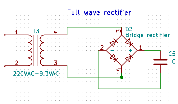 |
The full-wave rectifier is the basis of the Cockroft-Walton full-wave multiplier.
The DC output voltage of a full wave rectifier is about half the peak to peak voltage of the AC input, but it is cleaner than the half wave rectifier.
It looks like this:
| AC voltage | DC voltage |
|---|---|
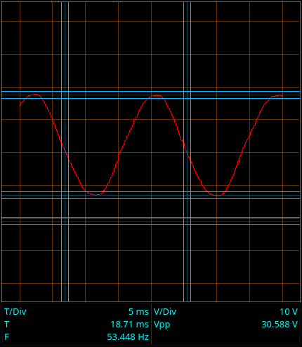 |
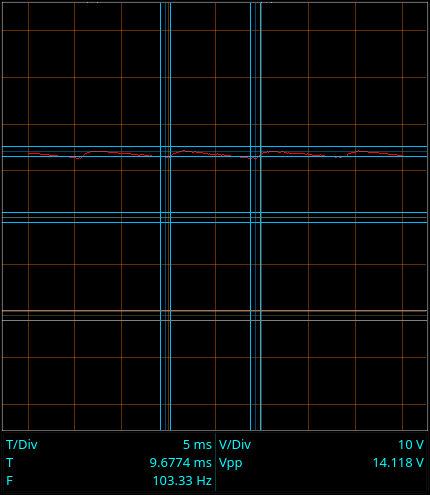 |
That’s 30V peak to peak AC, and a little less than half of that for the rectified DC - that’s 14VDC. Add in the 1V for the diode loss, and it looks good.
This is a single stage of a Cockroft-Walton full-wave multiplier:
| Cockcroft-Walton single stage |
|---|
 |
Look closely at the rectifier drawing and the Cockcroft-Walton stage. They are electrically the same. The capacitor is just moved to the center of the bridge. There’s a reason for that difference in the drawing style, but I’ll get around to it later. The capacitor in the center is also the reason I used Inkscape for this drawing. KiCAD won’t let you place parts at 45 degree rotation, and the pre-defined bridge (which has the diodes at 45 degree angles) is too small to put the capacitor into.
A single stage of a Cockcroft-Walton multiplier doesn’t actually multiply. It only puts out the same DC voltage that a rectifier would. This is different from the Villard or Greinacher circuits. Each of those gives a DC voltage of approximately twice that of a simple rectifier.
To get higher voltage out of a Cockcroft-Walton multiplier, you must use multiple stages. Each stage is connected in parallel to the AC source, but the outputs are put in series. Let’s see what that looks like:
| Not really a multiplier |
|---|
 |
That won’t work. We have a DC short circuit (through the diodes) across the transformer. That does horrible things to the AC input. Since the transformer can’t put out enough current to destroy any of the parts (the diodes are all rated for 1A, remember) I’ll just go ahead and have a look:
| A bad idea |
|---|
 |
That’s really far from being a multiplier.
What we need is to have the AC inputs to the rectifiers in parallel, but with out allowing a DC short circuit. Capacitors don’t pass DC, so let’s use capacitors to break path of the DC short circuit:
| Two stage Cockcroft-Walton multiplier |
|---|
 |
Here’s what the output looks like:
| DC voltage |
|---|
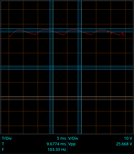 |
That’s 25.6 VDC on the output. Not quite twice the voltage of a single stage, but pretty good. A single bridge rectifer got 14VDC out, ideally we’d get 28VDC out of two stages. 1 VDC has gotten lost somewhere. Where did it go?
The capacitors ate it. Capacitors block DC, but they also have AC impedance. I’ll go into that in a later post.
For now, let’s see what adding another stage does:
| Three stage Cockcroft-Walton multiplier |
|---|
 |
| DC voltage for the three stage multiplier |
|---|
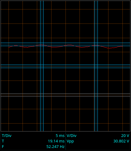 |
That’s …umm… not impressive. There ought to be about 42V there, but it’s only 30V. That last stage doesn’t seem to have helped much.
What’s going on here?
Remember I said the capacitors ate it? Well, they ate more this time around. I’ll go in to the causes and explanations later. For now, I’ll just say that how much the capacitors eat depends on the load, and my old oscilloscope is more of a load than my voltmeter.
Let’s check the voltages with the meter instead of the scope.
| Stage 1 | Stage 2 | Stage 3 |
|---|---|---|
| 16.6 VDC | 32.4 VDC | 46.6 VDC |
Each stage adds the same voltage as the first stage (more or less.) There’s really three times the voltage available at the output, as expected. Well, almost. Even my voltmeter is a bit too much of a load.
In summary:
- Cockcroft-Walton multipliers provide a DC output.
- Each stage provides the same DC.
- The DC out of each stage adds to increase the total output voltage.
- The total voltage is the voltage of one stage multiplied by the number of stages.
- Higher output voltage just requires adding more stages.
- You have to consider the load when designing a Cockcroft-Walton multiplier.
The next post will go into why the Cockcroft-Walton has the structure is has. There is a very specific advantage to the structure - even though the structure is also the responsible for the load problem.