Voltage multipliers - Part 8 Wrap up
Enough’s enough.
Voltage multiplier experiments - Table of Contents
Now that I know how to calculate the reactance of a Cockcroft-Walton voltage multiplier, I figure it’s time to give it a rest.
I really only wanted to get an understanding of the voltage doubler in my old oscilloscope, and clear up my understanding of the darned things after some discussions over on the Electrical Engineering Stackexchange.
My first real interest in voltage multipliers started when the high voltage section of my oscilloscope exploded.
It exploded the first time in about 1996. Loud “Bang!” and flames shooting out of the top of the ‘scope. That first time around, I figured it was my fault. I had laid a notebook (spiral ring binder with paper, not a laptop computer) on top of the ‘scope and blocked the cooling vents. The high voltage section was right under the notebook. The explosion tossed the notebook across the room. I had a complete spare high voltage module, so that first time I just swapped it out and got on with what I was working on.
The second time around was only a few years ago. I was checking out the RF detector output on my 12GHz RF camera when I heard something inside the ‘scope start to sizzle. I unplugged it fast enough to prevent an explosion. This time around there was just a subdued “foop.”
I had a spare capacitor to replace the one that popped, but the ‘scope still didn’t work. After much (very careful) troubleshooting, I came to the conclusion that the high voltage section was shot.
Here’s the schematic of the high voltage section of my old Telequipment D43:
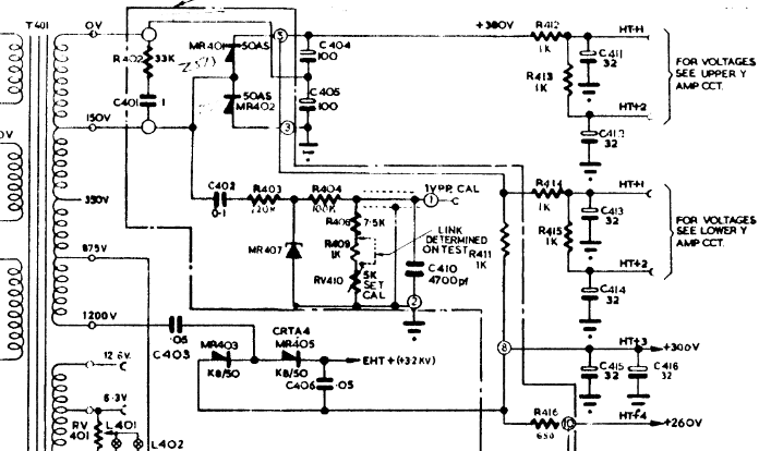
The section that caused the problems is built around C403, C406, MR403 and MR405. The input is 1200VAC and the output is 3.2kVDC.
If you rearrange it slightly, you find that it is a Greinacher voltage doubler - which is (as I’ve learned) the same as a single stage of a Cockcroft-Walton voltage multiplier.
Here’s a neater drawing of just the high voltage section:
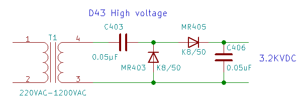
The K8/50 designation on the diodes refers to a stack of 50 selenium disk rectifiers in a tube to make a high voltage diode. (Datasheet found on the “Vintage Radio” forum.) The K8/50 has a peak inverse voltage of 3400V - and the voltage for a single stage Cockcroft-Walton multiplier with an input of 1200VAC is 3394VDC. I guess that finally explains what part caused the explosion. A diode died from a slight voltage hiccup and took the capacitor with it, and killed the other diode while it was at it.
Given that the forward voltage of a single selenium rectifier is 1V, and that there’s two stacks of 50 involved, the actual output voltage of the D43 high voltage section would be closer to 3294VDC (theoretical maximum less the forward voltage of the diodes.) Add a bit of a load, and the stated 3.2kVDC in the original schematic looks about right.
Well, I guess I’ve learned enough to understand my old ‘scope and its problems. Not that I’ll never have to deal with that particular problem again. I have long since replaced the finicky old selenium diodes with modern parts. While I was at it, I replaced the capacitors as well.
The final result looks like this:
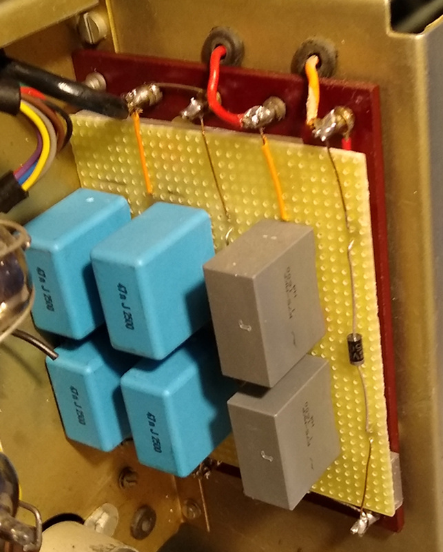
I ended up finding single diodes rated for well over 3500V, so I removed the strings of 1N4007 diodes I had first tried. The capacitors aren’t rated for over 3000V, so I used a combination of capacitors in series and parallel to get the correct capacitance and voltage rating. It was cheaper that way. It was cheaper (by far) to use 4 capacitors rated for 2500 volts than it was to get a single capacitor rated for over 3500 volts.
That’s pretty much the story of how I ever got involved with voltage multipliers.
What would I do if I ever needed to design a voltage multiplier?
It’s kind of complicated. A lot goes into it, and some of those things have less to do with the theory and more to do with practicalities. The folks that designed my old ‘scope had to balance a lot of things, not least of which was the availability of diodes with a high peak inverse voltage rating.
Relatively low output voltages (below 1000VDC) should be pretty straight forward. There are commonly available capacitors and diodes that can handle the needed voltages, and they aren’t especially expensive. Higher voltage gets complicated because you have to consider the availability of parts with the needed ratings, and the cost of those parts. Designing a high voltage multiplier can easily turn into multiple rounds of varying the frequency, the transformer, the capacitance, and the diodes until you find a compromise that meets all the requirements for power and voltage output but that doesn’t break the bank.
Large capacitors mean you can use more stages before the impedance gets out of hand, but large capacitors cost more at high voltage.
You want to use as few stages as possible, but that can mean a higher output voltage from the transformer - which is also more expensive.
You can raise the frequency to reduce the impedance, but then you have to have a power oscillator at the low voltage side capable of driving the whole mess.
You’ll end up juggling all of that and more to build a working multiplier that can meet specific requirements.
I’d make a first stab at it by selecting the following factors:
- Input voltage
- Transformer output voltage
- Frequency of the power source $F$ (AC line voltage, or driven by a power oscillator?)
- Needed output voltage $VDC_{out}$
- Largest affordable capacitors rated for at least the peak to peak voltage of the high voltage AC.
- Affordable diodes rated for at least the peak to peak voltage of the high voltage AC.
- Load $I_{load}$ (current draw) of the high voltage consumer.
You need a transformer with a secondary peak voltage that can be multiplied by some integer to get your output voltage. So, $2 * n * E_{pk} \approx VDC_{out}$ (where $n$ is the number of stages.)
Next you feed all that into the equation I gave in the last blog post:
\[E_{out} = 2nE_{pk} - \frac {I_{load}}{2 \pi fC} (4n^3 + 3n^2 - n) - 2nV_{f}\]If $E_{out}$ is close enough to the required $VDC_{out}$ and you can afford the parts, you are done. If not, juggle parts and frequency until you can meet your requirements and still pay the rent.
Edited 2020-04-18: Again, that equation applies to the half wave Cockcroft-Walton voltage multiplier.
I’m done. I’ve spent more time fooling with voltage multipliers than I intended, but I’ve also learned a good bit - and picked up another mystery to solve. I still haven’t figured out where the extra impedance is coming from when I measure the multipliers. I’m pretty sure that it is an artifact of the way I make the measurements and that it doesn’t really exist. I just don’t know how to explain it. That’s a project for another day.
Right now, I’m going to find something simple to do.