Learning about GNU Radio - Hooking up the impedance tester
Pretending I don’t have a room full of tools and equipment.
Learning about GNU Radio - Table of Contents
It has taken a while to get back to this. I promised in one of my last posts that I’d show how to hook up a speaker and measure its impedance with the simple impedance tester.
I spent most of my free time in the last month renovating a room and then moving all my hobby junk into it. I’m still sorting stuff into cabinets, but I’ve got enough junk out of the way to be able to work in here. I’ll show it to you when I’m done, but for now I want to wire a speaker to a PC and measure some impedances.
Since this program is intended to be used by novices (beginners) I figured it’d be a good idea to pretend that I don’t have all kinds of nifty tools and cables and stuff and just do it the way you might have to if you are just getting started with electronics as a hobby.
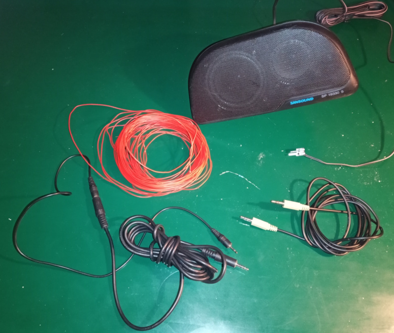
To test the impedance of a speaker, you’ll need a few things:
| Bits and pieces |
|---|
 |
As a list:
- Two stereo 1/8 inch cables. Also known as “aux cables.” They have a 1/8 inch (2.5mm) stereo headphone plug on each end. If you don’t have two, borrow a couple of them from a friend. The way we’re going to do this won’t hurt the cables - you can give them back undamaged.
- Wire. I used telephone wire because I had a roll laying around. You’ll want something like 22AWG (0.8mm) - thick enough to work with, thin enough to wrap around the plugs without causing a short circuit.
- A resistor. I used a 20 ohm resistor, but the value isn’t critical. You need to know the value, but pretty much anything from 10 ohms to 1000 ohms is fine. A low wattage resistor is fine. The only source of power in the whole thing is the line out, and it can’t put out any power. I used a 1/8 watt metal film resistor.
- A speaker to test. Mine is an aftermarket car radio speaker that is older than both of my (college aged) kids.
- A PC with a sound card that has line in and line out connections. A microphone connection won’t do. The software needs two inputs, and the microphone jack only has one audio path.
- The Simple Impedance Tester files. Download the .zip file and unzip it somewhere where you can find it again.
We’re going to use all of those things to build this circuit:
| Impedance tester circuit |
|---|
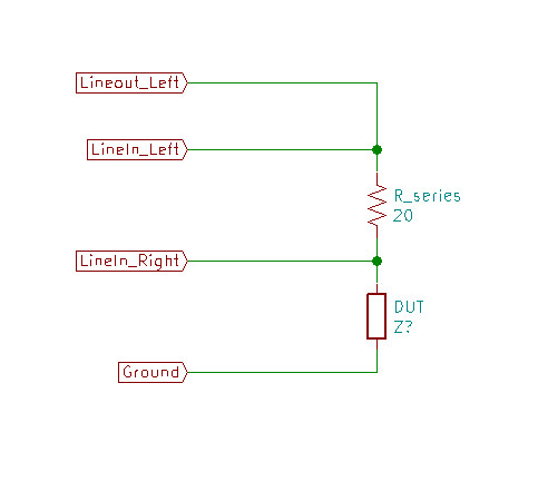 |
Step one is to cut and strip some pieces of wire. I cut four pieces of wire about 4 inches (10 cm) long and stripped about an inch (2.5cm) of insulation from the ends.
I used a pair of wire cutters to clip the wire, but a pair of toe nail clippers will also work. I used my pocket knife to strip the wires, but the back edge of the blade of a pair of scissors works as well.
Hold the wire in your left hand, and press the end of the wire between the knife blade and the thumb of your right hand about one inch (2.5cm) from the end. Press hard, and just pull the insulation down the wire away from your left hand.
Like this:
| Stripping wires |
|---|
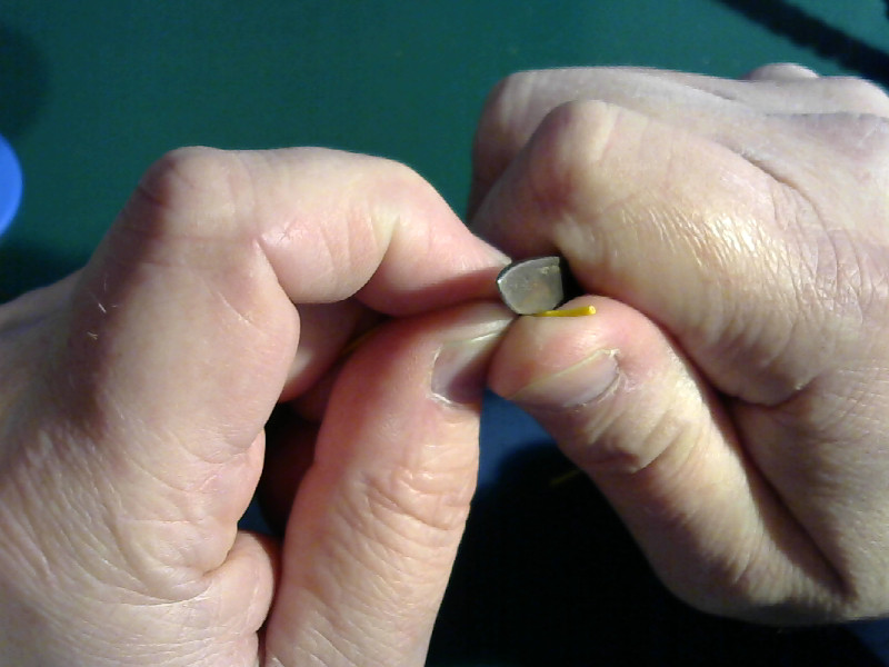 |
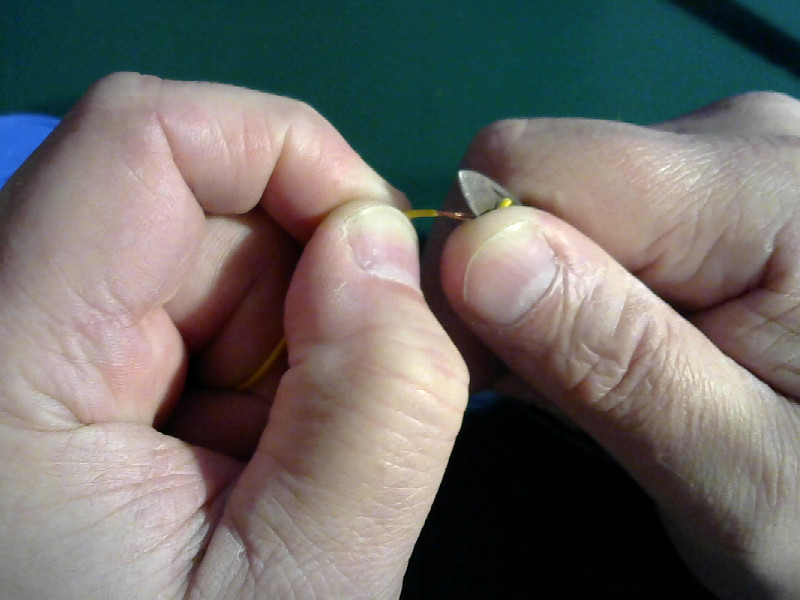 |
| Note: The blade I use to strip wires is intentionally dull. If you use a sharp knife then you will cut your thumb open. That hurts. I’ve done it. The back edge of the blade of a pair of scissors is sharp enough to strip wires with, and won’t cut your thumb. |
I find it helps to build things if I can print out the plans and lay them on the workbench to refer to as I am working. Print out the circuit diagram from above, and lay it out together with your parts.
| Ready for hookup |
|---|
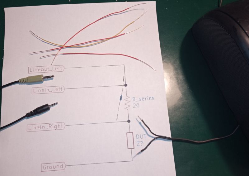 |
Now connect the wires and the parts as shown in the diagram.
The green cable (the top aux cable in the picture) is the line out from the PC. The other one is line in.
Here’s what mine looked like when I got done:
| Connected circuit |
|---|
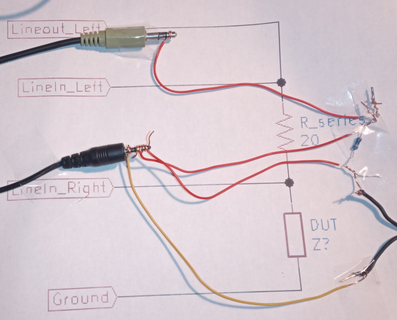 |
Take a look at the one wire connected to the green aux cable. You can see (fairly) clearly that I just wrapped the wire tightly around the plug a couple of times.
Each cable has two signal connections and one ground connection. The signals are on the tip and the middle ring of the plugs. The ground connection is at the base of the plug (also called the sleeve.)
You may notice that I only connected the ground wire from one plug. The ground connections for both plugs are connected together in the PC. Normally it is better to connect both ground wires to the circuit, but we’re going minimalist here. The circuit will work just fine as shown.
Be careful making the connections to the plug for line in. You’ve got three of them to make in a very small space. You may want to tape them in place to prevent short circuits. I taped mine down on the circuit diagram with clear tape so that you could see how the connections are made.
The connections to the resistor and the speaker are made simply by twisting the wires together. Again, you’ll need to make sure that the wires only touch where they are supposed to. Any unintended short circuits will make the measured values wrong.
Plug the line out cable in to the line out jack on your PC. That’s usually color coded green.
Plug the line in cable in to the line in jack on your PC. That’s usually color coded blue.
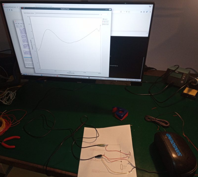
Start the GNU Radio Companion, and open the Impedanceplotter.grc file from the folder you downloaded from the Github Simple Impedance Tester repository.
Set the value for “Series Resistor” to the value of the resistor you used to build the circuit.
Click the “Run” button or use the “Run/Execute” menu to start the impedance tester.
If you’ve wired everything properly, you should hear a hissing noise from your speaker and the impedance trace on the screen should start moving towards reasonable values.
Moving the mouse around the display will show measurement values (frequency and ohms) for the point under the mouse pointer. There’s also a grid to help with making measurements.
It all looks like this when it is hooked up and running:
| Running impedance tester |
 |
It is easier to hookup if you have crocodile clips. You could also build a small circuit board using a piece of perf-board to solder all the connections. A custom made printed circuit board (PCB) would be kind of overkill, but might be a good first experiment if you want to try etching your own PCBs.
That’s pretty much it. It’s pretty simple to set up and use - except when it’s not.
As simple as it looks, there are still lots of places for it to go wrong.
I’ll give you a list of the most common problems and how to fix them here. If you set it all up and follow all the troubleshooting steps and still can’t get it to work then leave a comment below and I’ll try to help out. Or, login to Github and post a bug on the Simple Impedance Tester project page.
Troubleshooting:
- No hiss: Check the volume control for your sound card and make sure it isn’t muted. Check the wires from line out to the speaker and the ground - make sure they have good contact and aren’t shorted anywhere.
- Negative number for the impedance: Swap the two signal lines on the line in connector.
- Crazy squiggles that don’t make any sense: Check that all the connections are good and that there are no short circuits.
- Really high impedance values: Squeeze the connections tight on the plugs, and make sure the twisted connections are good.
In general, the mixer program on your computer is a good place to start looking when things don’t work. A muted line in can cause all kinds of odd measurements, and a muted line out isn’t good either. The levels don’t matter much, so long as the left and right channels are equal. The way the software works, it is not picky about the levels of the signals you use.
Some computers have more than one sound card, or sometimes the monitor counts as a speaker. If you’ve got two sound cards, then you’ll have to swap plugs around until you get it sorted out. If your operating system (Windows or Linux) is using your monitor as a speaker though the HDMI or DisplayPort connector, then you’ll have to twiddle with the operating system configuration to make it use the line-out of the sound card.
That ought to get you up and running. If not, drop me a line and I’ll try to help out.
P.S.
Don’t worry about short circuits. They won’t harm your computer. The only signal source in the whole setup is the line out, and it can’t put out enough power to damage anything. Even shorting line out to ground won’t hurt it.