Learning about GNU Radio - Sources of error in the impedance tester
That’s got the inductors covered, but what about the capacitors?
Learning about GNU Radio - Table of Contents
I’ve been thinking about the inductance and capacitance functions I implemented in the impedance tester a while back.
The inductor measurement especially bothered me. The curve was just so far from what I expected that I kept trying to figure out the source of the problem.
I kept running through the equations and curves in my mind, and finally came to the conclusion that the equivalent series resistance (ESR) was the most likely culprit.
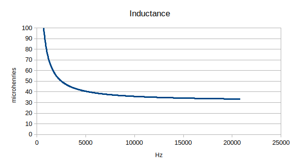
For reference, here’s the plot of an inductor I built and tested:
| Inductor |
|---|
 |
An ideal inductor should have a flat plot - the inductance should be the same for all frequencies. This plot isn’t flat. I mean, the impedance tester has limits set by the hardware - I expect inaccuracies above about 19kHz and below maybe 50 Hz. In between, however, I expect the hardware to behave.
In this case, there’s nothing much the hardware can do. It isn’t at fault.
The fault is in having to use real materials to make the coil. Wire has resistance. It doesn’t have much, but even a fraction of an ohm is a lot in comparison to the impedance of a (nominally) 31 microhenry inductor at low frequencies.
Lacking ideal materials to make coils from, I put together a spreadsheet with capacitor and inductor impedance calculations using Libre Office Calc.
The spreadsheet computes the impedance of an inductor (and capacitor) over the audio range (up to 20kHz.) It then adds a small amount of resistance to the impedance and calculates the inductance (and capacitance) from that (slightly) increased impedance.
The result does a very good job of explaining the extreme curve I got. A little experimentation showed that the 31 microhenry coil I made has an ESR of about 0.3 ohms.
0.3 ohms isn’t much, but a 31 microhenry coil doesn’t reach that much impedance until about 1600 Hz. Below 1600 Hz, the ESR dominates the impedance measurement - and it is pretty much a constant. Impedance due to the inductance drops as the frequency drops, but ESR doesn’t change.
Here’s the plot of an ideal inductor with 0.3 ohms of resistance in series with it:
| Simulated ideal inductor with 0.3 ohms in series |
|---|
 |
The curve pretty well matches the one further up there that I measured with the real coil - ignoring the “tails” due to the hardware limits, of course.
Specifically, the simulated coil with 0.3 ohms ESR hits 40 microhenries at 5000 Hz just like the real measurements do. That’s an easy point to pick out of both graphs.
It looks like I’m going to have to account for ESR when making measurements.
ESR unfortunately doesn’t explain the dip in the capacitance measurement:
| Capacitor |
|---|
 |
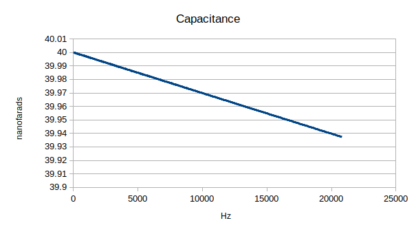 |
There’s something else going on that I haven’t got a handle on yet. The error there is also at low frequencies. Adding a series resistance to the ideal capacitor causes an apparent drop in capacitance at higher frequencies - and it is pretty much linear.
It also isn’t inductance. Inductance would cause an apparent drop in capacitance at higher frequencies.
I’m out of ideas right now.
If any of ya’ll have an idea, drop me a line in the comments, OK?