HowTo: Solder by hand - Remove through hole parts
Not the way most folks expect.
HowTo: Solder by hand - Table of Contents
Check this handy chart to find the temperature you need for this task.
I’ve got several things to share on this subject:
- Non-standard
- Things you need
- Things you can’t do
- The plan
- Salvage a part for re-use
- Replace a broken part
- Final words
I’m going to have to skip describing how to remove the solder from the holes for now. I haven’t used my solder sucker in years, and I’ve lost it. I have a new one on order, and I’ll write up how to clean out the holes in another post later. Amazon says my new solder sucker will be delivered by 26 February, so I won’t be writing that post for a couple of weeks.
Non-standard
I don’t remove parts the way most tutorials show. The typical tutorial says to remove the solder then pull the part out.
Ten years of practical experience using a soldering iron everyday shows that removing the solder first causes much more damage than the tutorials lead you to expect.
I remove through hole parts by removing the part first and then removing the solder. I’ll explain how in detail later, but for now I’m going to explain why.
In an ideal world, a device pin soldered to a printed circuit board (PCB) would look like this:
| Ideal soldered pin |
|---|
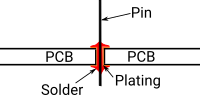 |
Reality looks more like this:
| Pin | Description |
|---|---|
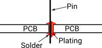 |
Offcenter |
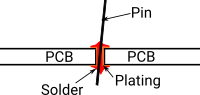 |
Slanted |
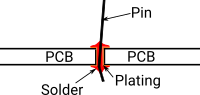 |
Slanted and bent |
When a pin is offcenter or slanted, it will trap solder in a place where you can’t suck it out with your pump. You’ll never get the part out when that happens. If you try to force it, you’ll end up pulling the plating out of the hole and taking the solder pad around the hole with it.
If you had an ideally soldered pin, then you could heat the joint, remove the solder, and pull the pin out.
Reality is a quite a bit different. Even if by some miracle the pin were perfectly soldered, the moment you start trying to remove the solder, you’ll move it and it isn’t perfect anymore.
The typical methods only deal with the ideal case, but you’ll never encounter that situation. There’s no point in learning how to handle something you’ll never encounter, so I’ll just concentrate on how you can handle the real things.
Things you need
You’ll need a soldering iron (naturally.) You can use your normal soldering iron to remove parts. You will find, however, that there are parts you can install with your iron but then not be able to remove. You’ll also find that there are parts on existing boards that require more power to remove than your standard iron can deliver. I’ll go into those cases in a little while.
You’ll need a solder sucker. When I was doing this stuff daily, the guy I worked with and I compared different solder suckers. The best tool turned out to be this thing:
| Best solder sucker |
|---|
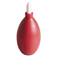 |
Those work well, though they seem to be harder to get these days. You squish it, place the tip over the joint and the tip of the solder iron, and let it pop back into shape.
Don’t bother with these things:
| Worst solder sucker |
|---|
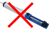 |
They kick when you trigger the release. Since the release is at the far end from the tip, you have no real control over what the tip does when the pump kicks. The kick usually causes the tip to skitter across the PCB, taking the soldering iron tip with it. That often tears the soldering pad from the board. No good. Don’t bother with them, no matter how cheap they are.
There are expensive desoldering irons with electrically driven vacuum pumps. All of my experience with them was bad. The filters plug up, and the tips wear out fast. When I used our expensive pump, I spent more time working on the tool than on the actual task at hand - and, when the tip wears out you can damage a PCB with it.
The best is really the simplest and cheapest.
I’ve already mentioned solder wick in a previous post. I prefer a relatively narrow wick. Make sure the solder wick you use has a type of flux suited to the type of solder you use.
Things you can’t do
Often times, one pin of a part will be connected to a large ground plane on the PCB. A ground plane is pretty much just a large sheet of copper foil in or on the PCB. They can conduct heat away faster than a typical soldering iron can pump it in. In such cases, you’ll need a bigger iron and a couple of tricks I’m not going to go into in this post.
Another thing you can’t do with a regular soldering iron is to remove and reuse through hole ICs or pin headers. There are usually too many pins spaced too far apart to be able to heat them all adequately with a typical soldering iron. There are special tools, or you can use a hot air desoldering station to heat all the pins at once. Since this series is about using a regular hand held soldering iron, I won’t go into how that works.
The plan
Rather than just show you how to remove a part, I’m going to carry out a typical hobbyist task: I’m going to salvage a part and reinstall it someplace else. Normally that would be “salvage from one PCB and reinstall on another PCB” but I’m using scraps to make my examples, so it’s “salvage from one PCB and reinstall to a different place on the same PCB.” You’ll just have to pretend I’m using two PCBs. :)
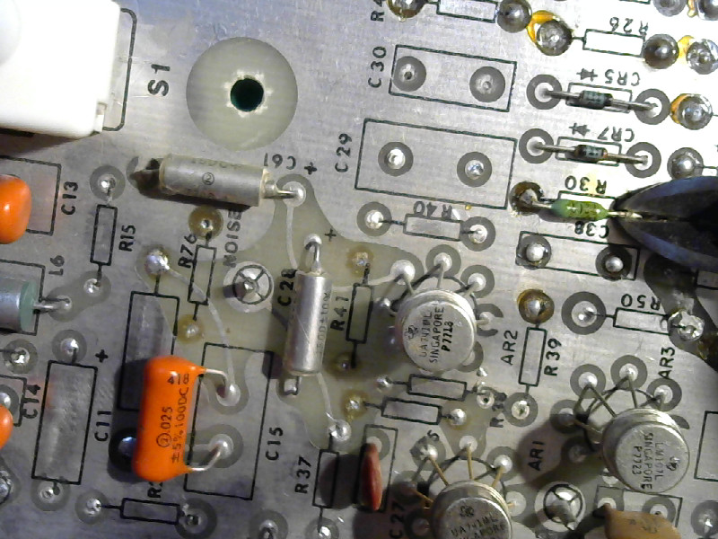
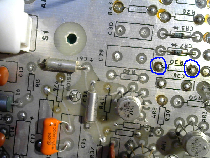
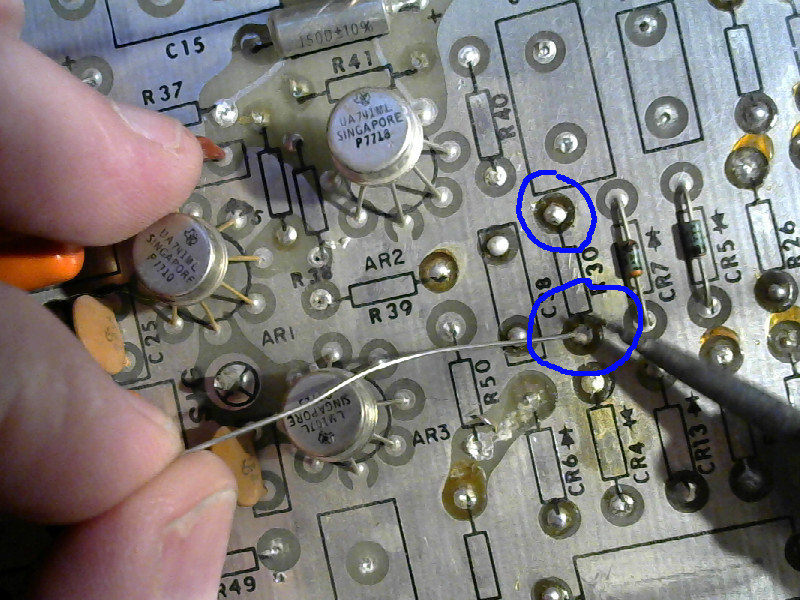
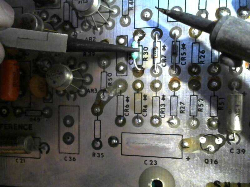
This is what I’m going to do:
| The task |
|---|
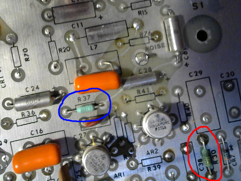 |
The resistor I’ve circled in red got too hot and needs to be replaced. I’m going to salvage the resistor circled in blue and put it in place of the one circled in red. That is, I’m going to replace R30 with R37.
Salvage a part for re-use
When you salvage parts, you are usually less concerned about the PCB you are removing the parts from, and more concerned about getting the parts out in good shape. When I salvage parts, I do it in a way that is (slightly) more likely to damage the board but is almost guaranteed to get the part out in usable condition. I mentioned it above - I just heat the pad and pin, and pull the pin out without removing the solder. Experience shows that you’ll damage the board more if you try to remove the solder, so I don’t bother.
Salvaging looks like this:
- As always, review the list of things you should always do when using your soldering iron.
- Add a spot of solder to the tip:
| Get ready |
|---|
 |
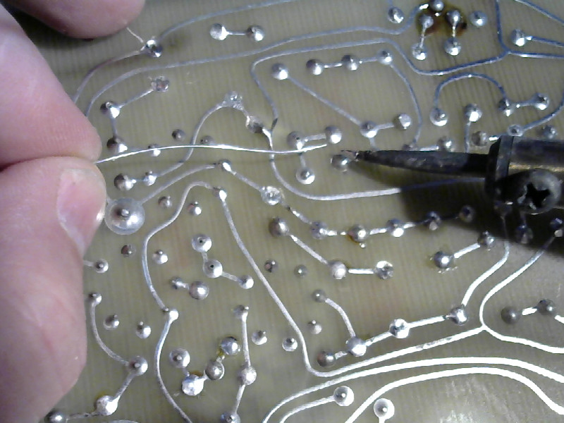
- Add solder to the joints of the part you want to remove.
| Add solder to the joints |
|---|
 |
 |
The one circled in blue is just to show that while you need some solder added to the joints, you don’t have to add a ton. If the pins are bent underneath the board, use the tip of the iron to push the pins straight. Careful, though. Pushing a pin straight can damage the plating on your soldering iron tip can cause it to wear out faster than it ought to.
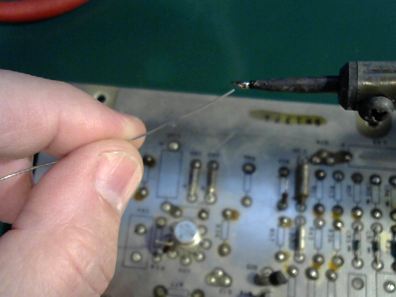
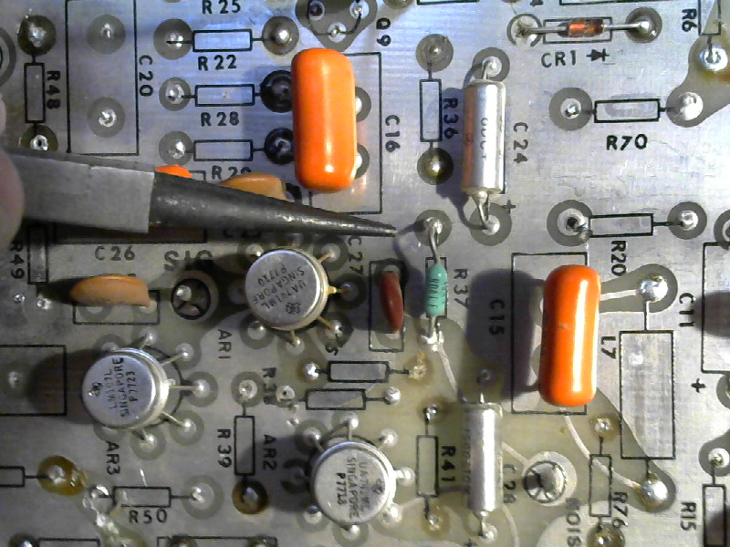
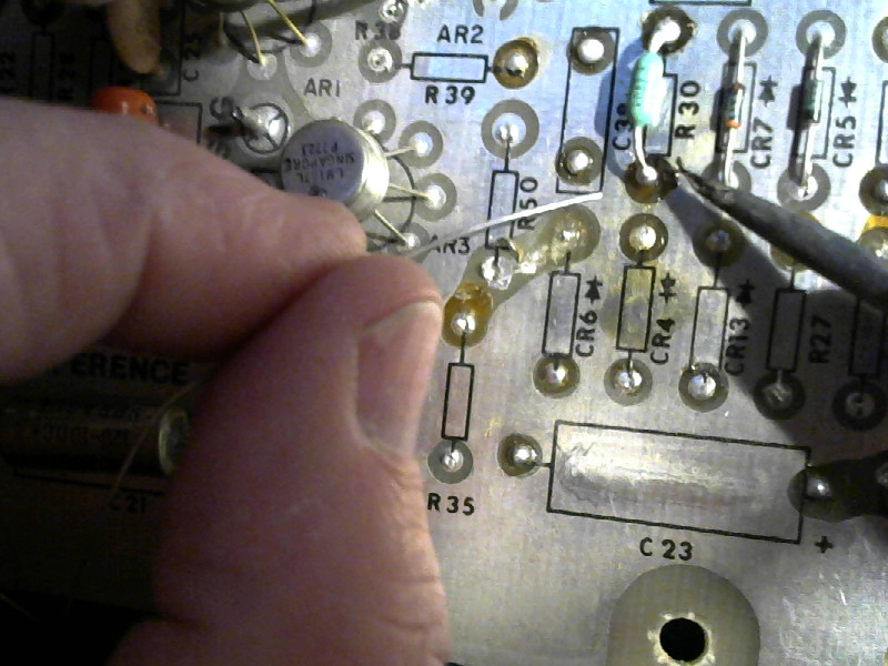
- Get hold of one pin from the top.
Use a pair of needle nosed pliers.
| Grab the pin |
|---|
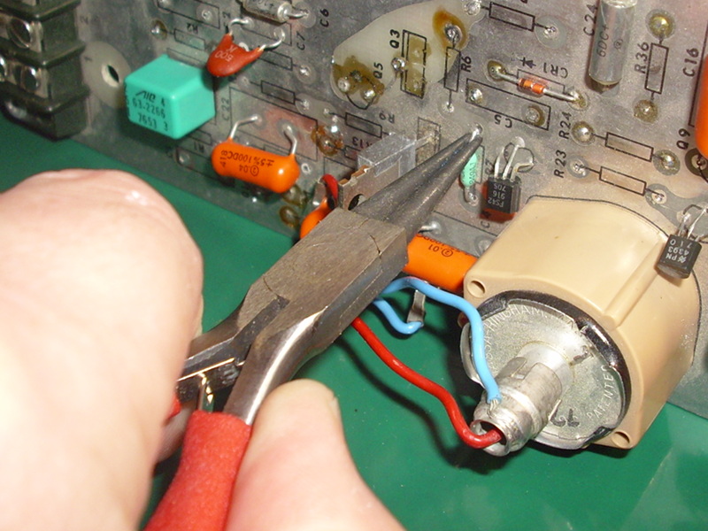 |
That’s not really the part I removed - that picture was out of focus, so I had to go back and stage a replacement.
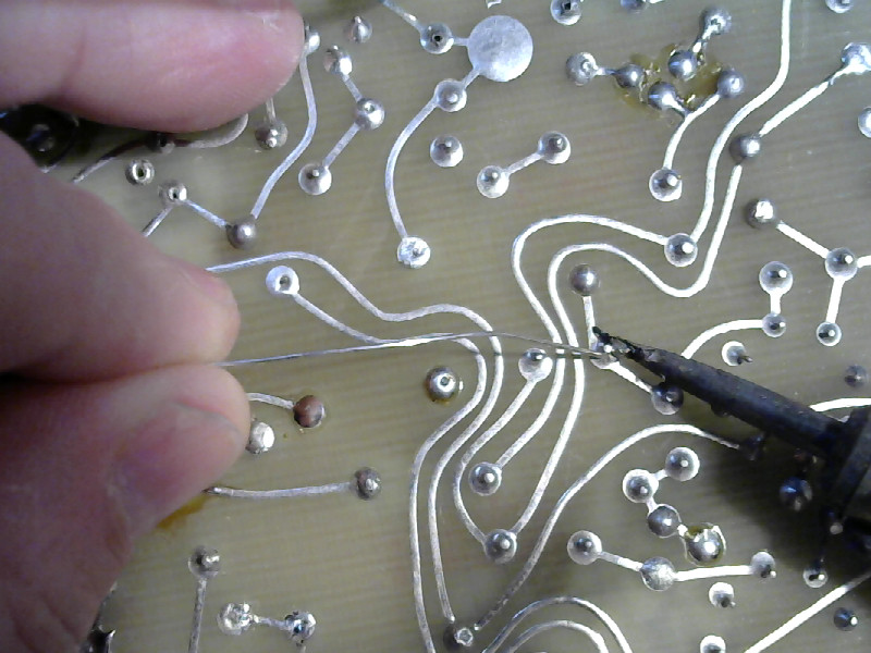
- Heat the pin from the bottom.
Find the pin you are holding with the pliers from the bottom side. Get a little solder on the tip of the iron, then heat the pin until the solder around it melts and flows - all the way through to the top side.
| Melt it loose |
|---|
 |
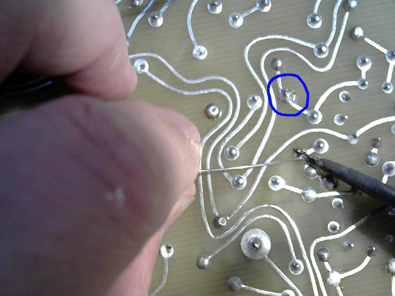
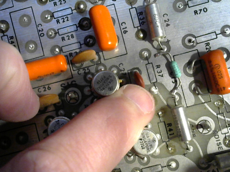
- Pull it out
With the tip of the iron still on the bottom of the pin, pull the pin with the pliers. It’ll come out. If all the solder is melted and liquid, then it’ll come out without destroying the through hole plating or the pads on either side of the board.
| Pull it out |
|---|
 |
That’s what it looks like when you’ve pulled one out. Now do the second just like the first.
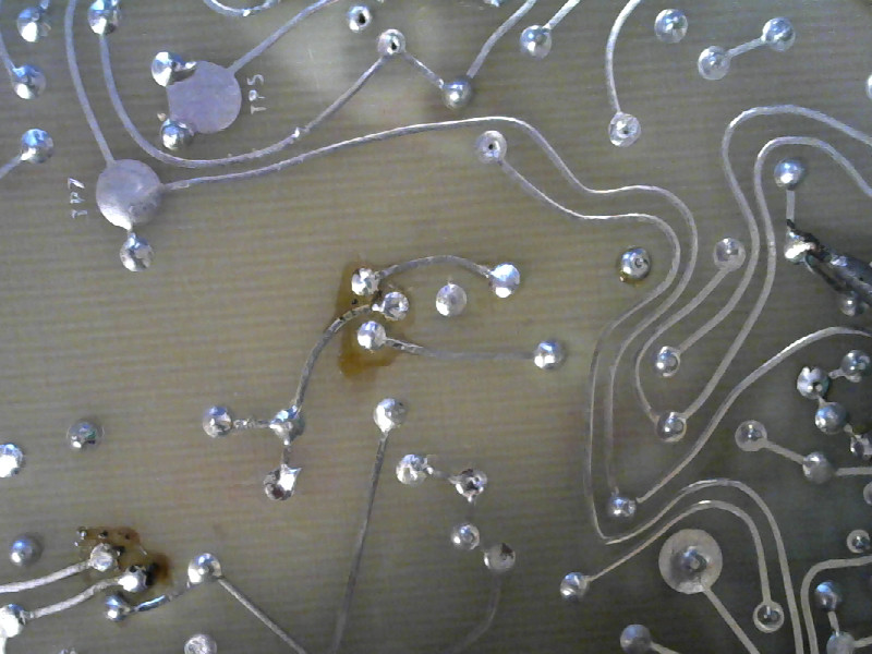
- Got it
If you straightened the pins, got a good bit of solder on the joints, and heated things adequately, then it’ll look like this when you are done:
| Done |
|---|
 |
No damage to the board, and the part is still in one piece.
Replace a broken part
If a part is bad and you know it, then don’t bother trying to get it out in one piece. Just clip the pins neatly to remove it, then remove the pins from the bottom side - or the top side, as may be needed.
Once the bad part is out, you can install the replacement without removing the solder from the holes.
Repair is about making it work without doing additional damage. Every bit of work you do on the board is another chance for something to go wrong, so do as little as possible to the board.
Now that we’ve got a spare part, we’ll go on and replace the bad one.
-
Again, review the list of things you should always do when using your soldering iron. (Yes, I mean it. Those are things that must become a habit. Re-read them and keep them in mind.)
-
Clip the bad part out.
| Clip out the bad part |
|---|
 |
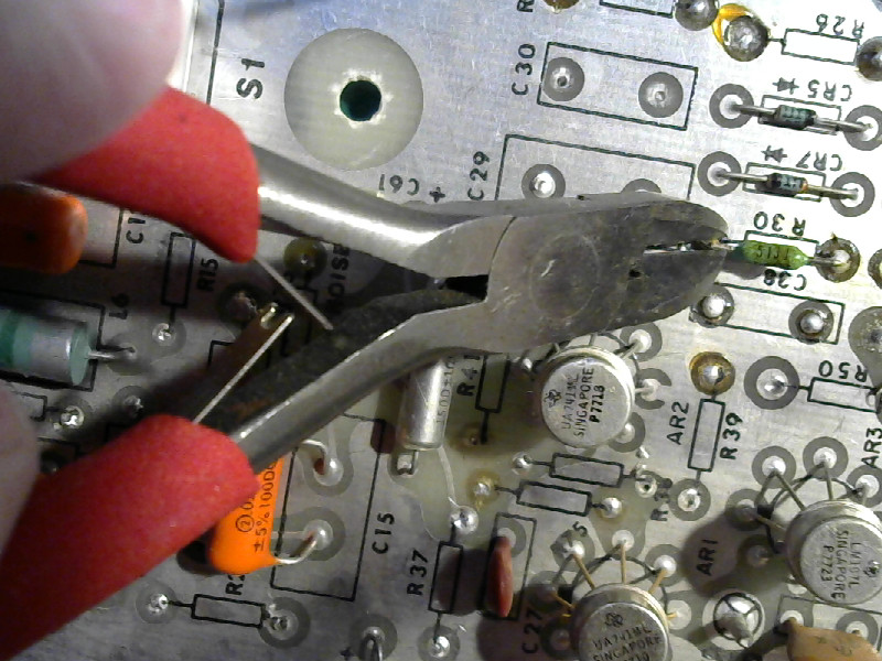 |
 |
The blue rings mark the pads I clipped the resistor from. You can see the ends of the pins poking up out of them.
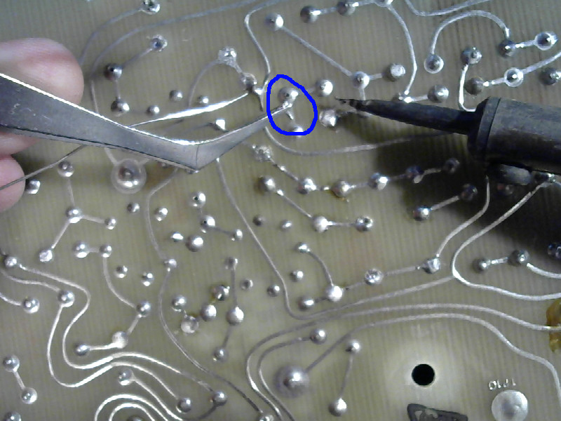
- Add solder and pull the pins out.
I usually remove the pins from the bottom side. If they are bent, then it is easier to get them out the bottom. From the bottom, you can grab the bent part of the pin and pull the straight part through the hole.
| Add some solder and pull out a pin with your tweezers |
|---|
 |
 |
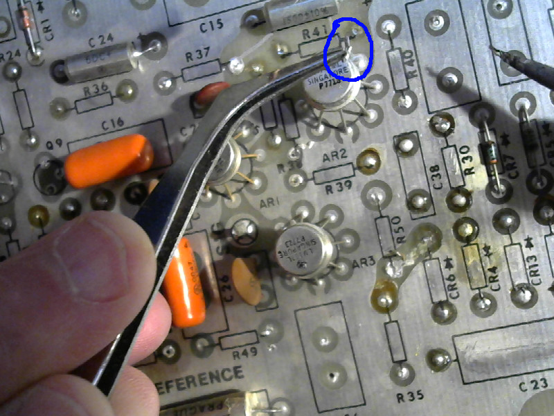
Sometimes you’ll need to work from the top side. In this case, the second pin fell back through the board so I turned it over and finished it from the top.
| Take it from the top |
|---|
 |
- Clean up.
Heat the pins where you pulled the pins out, and add dot of solder. The idea is to clean up any splatters of solder that might cause a short circuit. It’ll also give a you a clean place to solder in the replacement part.
| Clean up |
|---|
 |
- Prepare the replacement part.
I’m not going to push the pins of the replacement part through the board. I’m going to trim the pins on the replacement resistor so that they are just about 1 millimeter longer than they have to be to reach the board. I’m going to turn it into a sort of “pseudo surface mount” part.
Like this:
| Trim the pins |
|---|
 |
While you are at it, tin the ends of the pins.
| Tin the pins |
|---|
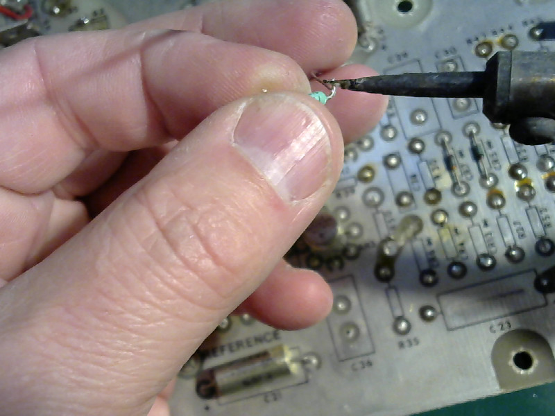 |
Heat each pin and then melt a little solder onto it.
- Install the replacement part.
Hold the replacement part in place with the tweezers, and heat the solder on one pad with the iron until it melts. Poke the pin into the solder, and while you are at it line up the second pin so it is in place to be soldered later.
| Tack the replacement down on one pin |
|---|
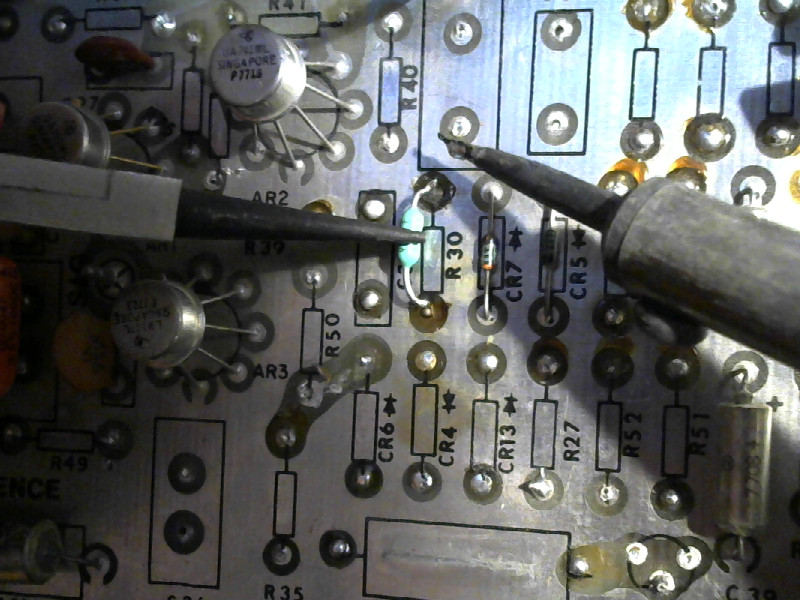 |
| Solder the second pin |
|---|
 |
Apply the tip of the iron and the solder to the pin and the pad, and solder like you would normally. (The pad came unstuck here despite my careful work. I had burned the resistor with a match to give it that burned out look, and that did enough damage that the pad came unstuck while I was cleaning up splatters. That can happen in real life, too. In this case, I can still connect to the through hole plating. In a worse case, I’d have had to try to push the pin through and solder it on the bottom side.)
Now touch up both joints (heat the pin and pad and apply a spot of solder.) The first one needs it because it wasn’t properly soldered - it was just stuck in place to hold things while the second one was being soldered. The second joint may not need it.
| Final cleanup - and done |
|---|
 |
Final words
I use that method of replacing parts on all sorts of things. It’s the easiest way to replace an IC - clip out the dead one, trim the pins on a new one, then solder the new one down without removing the solder from the holes.
Those two tricks will get you through a lot of things - but not everything. For some things, you’ll have to clear the holes, or you’ll have to pull a part out all pins all at once. I’ll go into those things in separate posts, but for now you’ve got enough to handle a lot of the stuff you will face as a hobbyist.