A sewing machine motor speed control - Using a photointerrupter for speed control feedback
Works about as well as could be hoped for.
A sewing machine motor speed control - Table of Contents
The last time I worked on the motor control, I found that measuring the RPM using back EMF was not going to work well, especially not at low speed.
To get a more accurate and stable RPM measurement, I ordered some photointerrupters and rigged a setup to test them.
After some initial difficulties, I got the photointerrupter to work like I wanted it and then adapted the PID controller routine I was using - more random changes to the PID constants until it worked smoothly.
The motor and photointerrupter setup looks like this:
| Motor and photointerrupter |
|---|
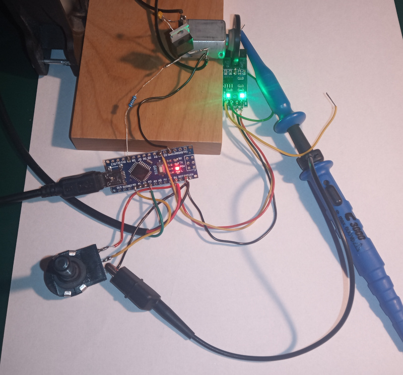 |
The wooden block is the base of the fan I use to blow away solder fumes while working - the motor is super glued to the block. I also used super glue to hold the photinterrupter in place. That won’t hold any kind of load, but it does OK for my little tests.
It runs smoothly down to a little under 400 RPM. At 360 RPM, it gets a little jumpy. The motor itself doesn’t like running that slowly - it has a tendency to get stuck. The PID controller recognizes when the motor stops and gives it a good “smack” to get it turning again. Given that the motor is built to run at over 15000 RPM, I don’t find it strange that it has trouble at low speed.
| Photointerrupter pulses at about 360 RPM |
|---|
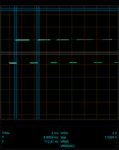 |
You can see how uneven the pulses are. That’s because the motor keeps stopping and the PID controller keeps restarting it.
The PID control managed to (mostly) hold the speed steady. I managed to press the nub of the shaft hard enough to completely stop the motor at one point in the video - and the PID controller wound things up to get it going again. The overshoot didn’t last too long - it was back at the set speed in about one second once it got going again.
I expect the real sewing machine motor to do better at low speed. The commutator on the sewing machine motor has more segments, so there are more chances per rotation for the motor to “give itself a push” than on the little DC motor (it only has three commutator segments.)
Since I had to order the photointerrupters, I went ahead and ordered a foot pedal to use in further experiments.
| Foot pedal |
|---|
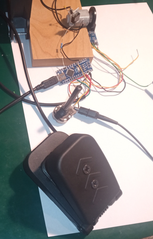 |
That’s a Hall effect foot pedal intended to be used as an accelerator pedal on gokarts or scooters. The action is smooth, and it won’t wear out like a potentiometer. You can see that I’ve already connected it to the Arduino in the picture there. I made the video using the potentiometer, but I’ve also tried controlling the speed with the foot pedal. I think it’ll be fine, and easier to “dose” than the mechanical monstrosities found on typical sewing machines.
Because of the way the foot pedal is built, I’ll have to mount it on something - the plunger with the magnet sticks out of the bottom of the housing when the pedal is pressed. I’ll probably mount it on a piece of wood so that my foot sits flat on the surface (sole parallel to the floor) when the pedal it all the way up - I want to push the pedal down. I find the usual sewing machine pedals uncomfortable in that they all have your foot bent upwards for stop/slow. My feet don’t like up. They like down.
With most of the conceptual problems cleared up, I’ll start drawing up a circuit for the controller and looking at how to mount the photointerrupter and its slotted disk on a sewing machine motor.