A sewing machine motor speed control - A long over due update
Collecting parts and drawing schematics.
A sewing machine motor speed control - Table of Contents
Working on the Pfaff model K reminded me that I have yet to finish the new motor controller for my Adler class 8 sewing machine. I have lots of projects in mind to sew with the Adler, but I don’t like to use it with the crazy controller the motor came with.
I sketched out a lot of the motor control circuit a few months ago, then ordered some parts from Mouser. They came in a good while back, but I’ve been busy with other stuff.
I got back to it a couple of days ago, and ordered a black aluminum box to put all the electronics in. I need the box first because I have to design the circuit board to fit inside it.
I’ve spent a few hours over the last couple of days putting together a schematic and sketching out a PCB to fit the housing I ordered. I haven’t sent the board out to be made because I want to compare the real box with the datasheet. The box should come in sometime in the coming week.
Datasheets are great, but sometimes I make mistakes in reading them. That bit me once and cost me the price (and time) of having new boards made. I prefer to check my datasheet based designs against the real, physical parts before ordering a PCB made. I print the finished layout on paper, cut it out, then lay all the ICs and other parts on it to check that I made the foot prints properly in KiCad. I check that the board will fit the box by dropping the paper cutout in the box.
| Schematic |
|---|
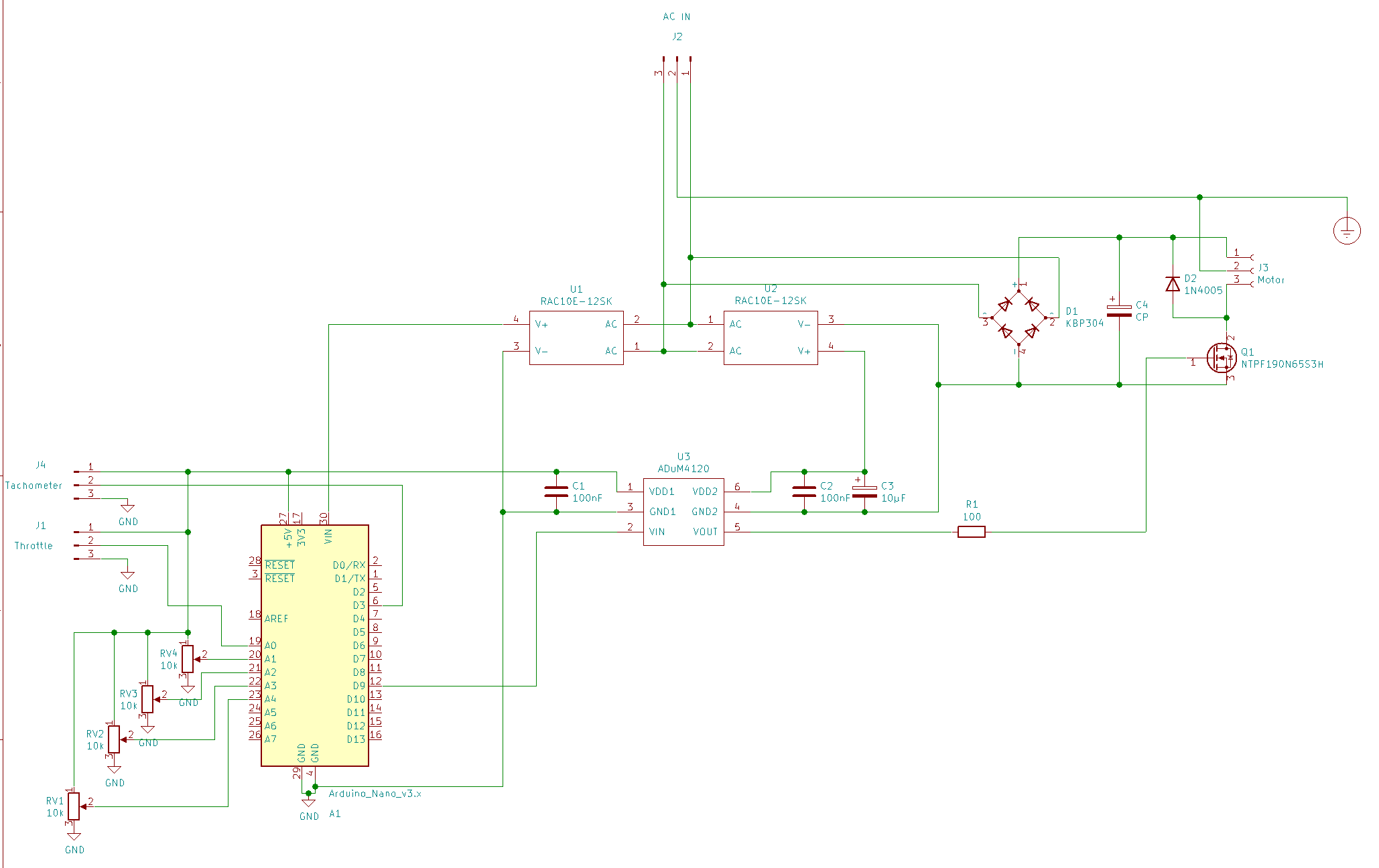 |
| Preliminary, do not use. |
The schematic and the layout will change before I have the PCB made.
Here’s the interesting bit of the circuit:
| Motor control |
|---|
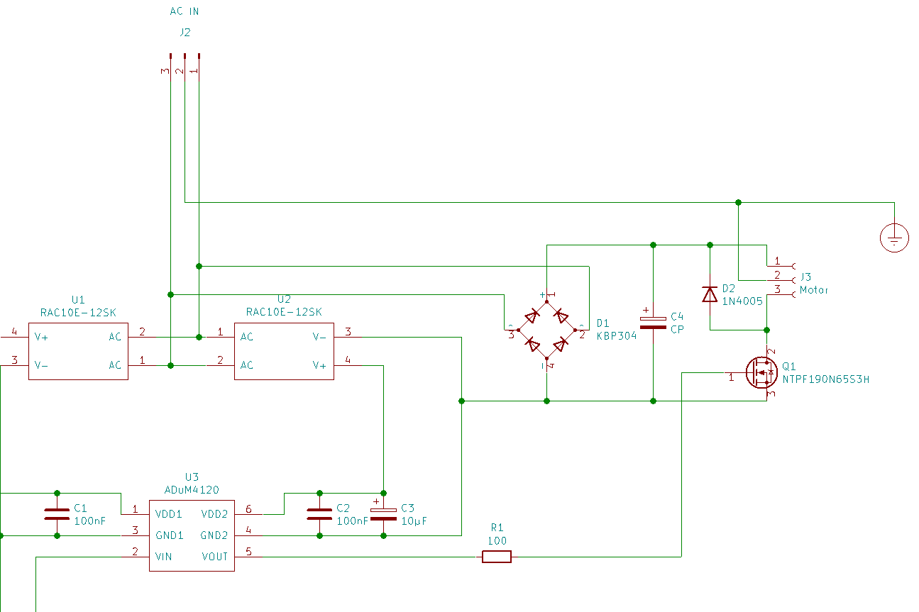 |
| Preliminary, do not use. |
There are two isolated 12V DC power supplies in there (U1 and U2.) I need two of them so that the Arduino is not at line voltage - I don’t want to get zapped by touching a supposedly safe “low voltage” line.
The ADUM4120 (U3) is an isolated MOSFET gate driver. Besides being able to deliver the (relatively) high current needed to quickly switch the MOSFET gate, it provides isolation between the low voltage (Arduino) side and the line voltage side of the motor control.
I will be driving the universal motor with DC from bridge rectifier D1. D2 is there to catch the “kickback” when the MOSFET switches off the motor. It should also “brake” the motor when the power is off - it should be possible to “stop on a dime” from full speed. Other controllers let the motor coast to a stop, which is not a good thing when you have a very smooth running machine with a really heavy balance wheel. People complain that electrically driven vintage sewing machines don’t stop precisely enough. This one ought to - that or blow the diode. We’ll see.
I picked the MOSFET (Q2) to handle a good bit more than the 330 VDC from the rectifier. It is also somewhat over dimensioned for current. While the motor itself shouldn’t draw anything near 1A, Q2 is rated for more than 10A continuous drain current. Q2 will be attached to the metal box using proper isolating heat sink hardware. That makes it absolutely necessary that the box be grounded - there’s a connection to “Earth ground” in the schematic to remind me to ground the box.
The Earth ground will be routed through the box to the motor. The typical cheap sewing machine motors aren’t grounded, which makes me nervous. This one will have a proper Earth ground to catch any catastrophic failure in the motor.
There’s a fuse in the circuit, though it is not shown. I’ve got a C14 receptacle to install in the box. It has a built in fuse holder. I’ll put like a 1 or maybe 2 ampere fuse in it.
Another thing I didn’t include in the schematic is the circuitry of the tachometer pickup. I intend to use the photointerrupter I used in my experiments. I’ve got several of them, and there’s no need to reinvent the wheel.
I’ll build a wooden pedal box to hold the Hall effect “throttle” pedal I mentioned in the photointerrupter post. I’ve got a snazzy locking three pin connector for it already - though I forgot to order the matching socket with the other parts. It’s on order now and should be here soon.
| Preliminary layout |
|---|
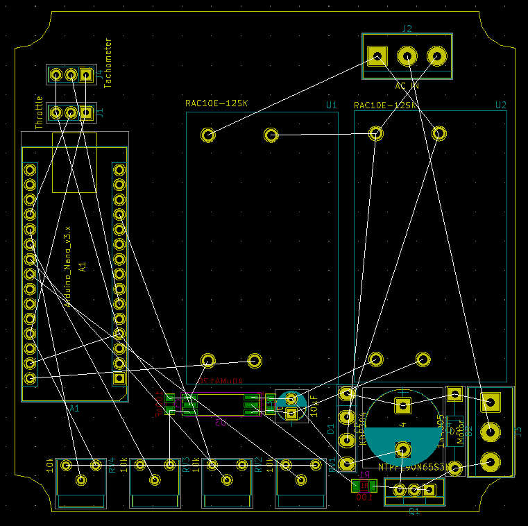 |
That’s all the parts placed on what I think is a properly sized PCB. There’s room along one side for the C14 socket and the socket for the throttle pedal.
I’ll check it all for fit this week, then finish up the layout and order the PCB. I ought to have everything ready to try out in a couple of weeks.
I think I’ll probably try it out unregulated (no feedback, just straight throttle position to PWM duty cycle) before implementing the PID controller.
I expect the most time consuming part of this whole thing will be in getting the software to do what I want. I want to add an “auto-tune” feature so that I don’t have to guess at proper PID coefficients. Oh, drat. I’ll have to add a button for “auto-tune.” I forgot that. Another day.