A sewing machine motor speed control - Putting things together
No smoke, but not quite done.
A sewing machine motor speed control - Table of Contents
It has taken another month, but I finally ordered the circuit board for my sewing machine motor control. I got all the parts together and verified the component sizes and pinouts, then did a final layout. I order my PCBs from Eurocircuits. They aren’t cheap, but I get the boards back within the week and don’t have to worry about import taxes and stuff because they make the boards here in Germany.
I soldered the components on the board last week then wired it to a motor last Saturday for a first test run.
| Ready for a first run |
|---|
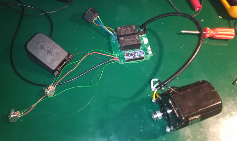 |
| (Yes, that’s a screwdriver from a Tonka toy kit laying there.) |
I am careful and rather paranoid about things that can kill me.
I assembled and tested the 300VDC circuit separately, first. I found that the fuses I had on hand aren’t sufficient when using the 47µF smoothing capacitor, so I took it back out. It’ll be in the final circuit. I was mostly concerned about the polarity of the bridge rectifier and that big capacitor. I checked first with just the rectifier and saw that the polarity was good. Then I installed the big capacitor and found that the (600mA, fast blow) fuse I had in the AC socket wasn’t a good choice. Well, I only used it because that’s what I had at hand. I have some 2A slow blow fuses on order.
Next were the two 12V power supplies. They are isolated (as advertised) and I got the polarity correct.
With the preliminaries out of the way, I installed the rest of the components and wired the motor and the Hall effect throttle pedal to the board.
I bashed together a quick program for the Arduino. It is a little bit more complicated than the simple program I used for my first PWM motor control experiment. The biggest difference was that I had to implement a “full stop” position for the throttle. There’s one potentiometer on the board that sets the threshold for the PWM to start up. When the throttle position is below that level (nobody is pushing on the throttle,) the Arduino sends a permanent “low” on the PWM pin. The commercially available electronic controllers have an extra switch as a lock out.
The first start-up was kind of scary. I don’t like playing with 230VAC, and I’m not used to working with “high power.” The motor is rated 100 watts - that’s a lot when you are used to piddling with digital electronic circuits with low voltage and milliamperes of current.
That first power-up showed a mistake in the circuit. I forgot to add a pull down to the PWM out. Until the Arduino finishes its power on sequence (including a two second wait for serial communications,) the digital IO pins are all floating. The gate driver I’m using (an ADuM4120) has a very senstive input - the floating Arduino IO pin was enough to pull the gate driver input high. This caused the motor to howl at full speed until the Arduino “woke up.”
The schematic has the pull-down on it now, and I added it to the layout.
It looks like this is going to go well. The motor can run at a staggeringly low speed.
Controller test:
At the start there, the motor is turning at something like one rotation per second. It can do that for as long as you want to hold there. That is ideal. Given the pulley ratios for the motor and the sewing machine, that works out to one stitch in six seconds - plenty slow enough for me to follow the sketched in decoration patterns on the things I sew.
I don’t have the feedback hooked up yet, so the motor is running “open loop” right now.
With electronics in hand, the project is now mostly mechanics and software.
I’ve still got a lot to do:
- Mount the PCB in the box.
- Mount the two potentiometers, the AC power connector, and the foot pedal connector in the box.
- Work out how to mount the box on the motor.
- Work out how to mount the RPM counter on the sewing machine so that it doesn’t stick out like a sore thumb.
I’m thinking of putting the slotted wheel and the photodetector in a small wooden box, with the box mounted on a brass rod to hold it in contact with the hand wheel on the sewing machine. That’ll hide the electronics and plastic bits in something that goes along with the machine’s appearance. There’ll be an aluminum pulley with a rubber tire on the box with another piece of brass rod as an axle driving the slotted wheel for the RPM counter.
Lots of sawing, filing, sanding, and “bash to fit” until it all goes together nicely.
The software will be a fair amount of the fun.
It’s making progress at last, though it may still take a while to get done. My wife and I are having the living room repainted and a new floor covering (fake wood parquet) installed to replace the worn out carpet. I’ll be dealing with that for the next couple of weeks and trying to sneak time to work on my projects.
I’ll put the circuit design and the software up on my GitHub page when it is all done and working. I don’t see much point in posting a half done bunch of junk.