A new camera for the D43
That was easier than expected.
My Telequipment D43 projects - Table of Contents
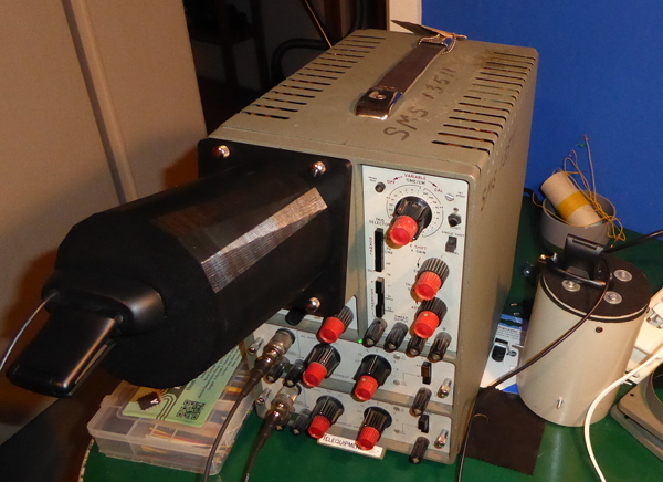
| D43 with the 3D camera and C270 Webcam |
|---|
 |
Some time back, I mentioned I was going to build a new camera to go with my oscilloscope camera software.
The plan was to build the new one pretty much like the old one, but with a better camera.
I got a better camera, alright, but ended up having the new camera mount 3D printed.
My son has been teaching himself how to use a 3D CAD program, and took up the challenge of drawing a 3D model of the camera I needed. I had it printed through a 3D print service since I don’t own a 3D printer.
Made the way it is, some of the things I had intended to do with the new camera turned out to be unneccessary.
- No need of adjustment when everything is precisely aligned from the get go.
- No need of extra black felt to make things light tight when it’s all made of black plastic and tight fitting to boot.
This is the camera mount and the Logitech C270 I’ll be attaching to it:
| D43 camera mount |
|---|
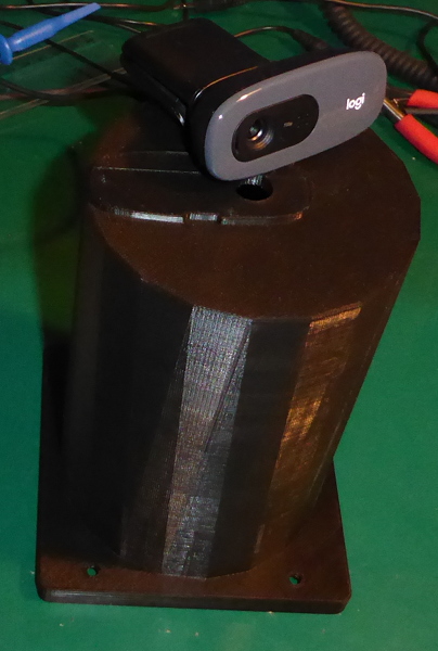 |
There’s a raised plate on the base there. It is shaped to fit inside the C270, and is modeled on the front plate of the webcam. The idea is to close things up light tight without having to use “gaskets” of black felt.
The mounting holes for the C270 were also part of the model - “printed” holes. The heads are countersunk on the inside so that I could reuse the original screws.
The C270 has a few advantages over the webcam I used before:
- Higher resolution
- Better imaging (better compression, better ADC, less background noise, etc.)
- Adjustable focus
That last surprised me, to be honest. From the outside, it looks like a fixed focus webcam. Once you get the front plate off, you’ll find that the lens has an adjustable focus. You don’t want to be fiddling with it all the time, but it sure makes it easier get good images from the scope.
I’m going to run through the assembly (lots of photos) then show a couple of pictures made with the old and the new camera.
To start off, the C270 has to come apart:
| Disassembling the C270 - front bezel |
|---|
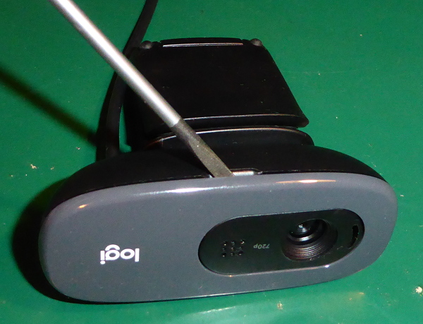 |
| Pop the front bezel off with a flat bladed screwdriver in the slot on the bottom. |
| Disassembling the C270 - front cover |
|---|
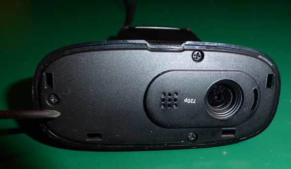 |
| Remove the three screws. |
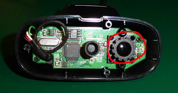
| Disassembling the C270 - remove the PCB |
|---|
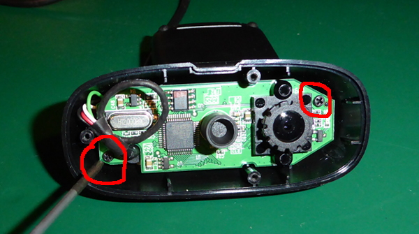 |
| Remove the two screws - marked with red circles. |
The C270 has a power-on LED. It faces into the camera mount (towards the oscilloscope screen) and would cause reflections. It has to go.
| Disassembling the C270 - removing the LED from the PCB |
|---|
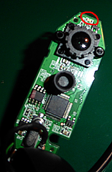 |
| The LED is marked with a red circle. |
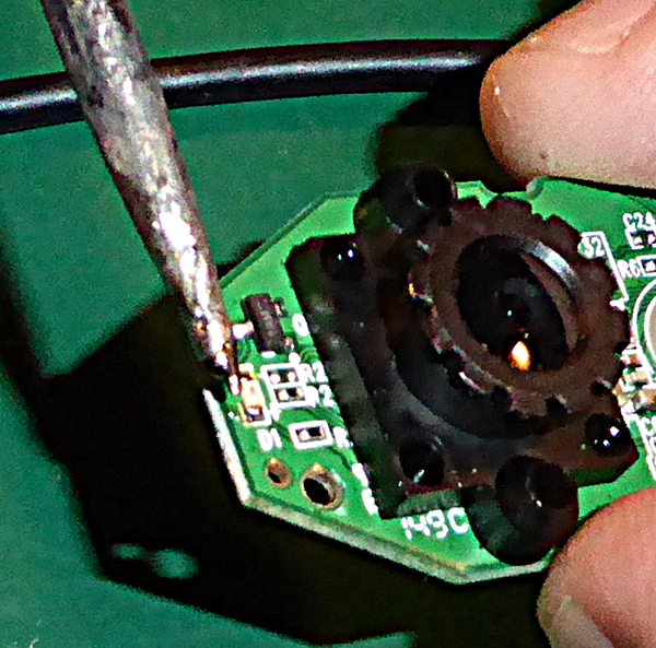 |
| Get a big blob of solder on the tip of the iron. Apply to the side of the LED so that both pads get heated. |
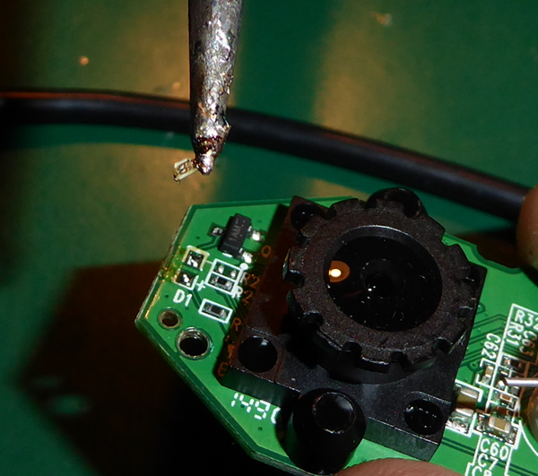 |
| Push the tip sideways and the LED will come off - and stick to the tip of the iron. |
The C270 has a built in microphone and sound card. I don’t want to accidentally record myself singing along to some scurrilous song while working, so the microphone has got to go.
| Disassembling the C270 - removing the microphone from the PCB |
|---|
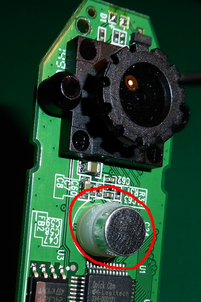 |
| The microphone is marked with a red circle. |
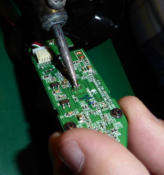 |
| Apply solder to both pins, and heat them both at the same time. |
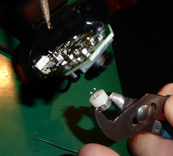 |
| Pull on the microphone with a pair of pliers while heating the solder from the other side. It’ll pop right out. |
Put the PCB back into the back housing of the C270 (no pictures, I figure if you got this far you know how it goes back together.)
Check the fit of the holes in the camera mount. 3D printed screwholes tend to be a little undersized and fuzzy. You want the screws to go in easily. Check the fit of the countersunk holes from the inside while you are at it.
| Cleaning up the screwholes |
|---|
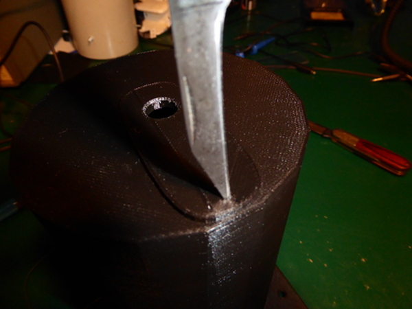 |
| Fussier folks may use a properly sized drill bit. I just whipped out my pocket knife and got to it. |
Once everything fits nicely, put the C270 aside.
Take the bezel off of the D43, and put the camera mount on so that the raised shape of the C270 is to the left. At this point, the pocket knife had more work to do. I had measured the position of the screwholes for the D43 incorrectly, and had to shave a couple of millimeters out of them so they’d match up with the screws on the D43. Lesson learned: Make paper printouts of critical parts and check them for fit before having 3D parts printed.
Make sure to get the grid and the green filter back in the proper place when attaching the camera mount.
Plug the C270 into your PC and fire up any webcam software you like (or even use the D43 camera software.) Check to make sure you are getting a picture from it, then hold it in place on the camera mount.
Adjust the backlight so that you can see the oscilloscope grid on your computer screen. Check the focus. Twist the knurled knob around the lens in the C270 and check again.
| Focus |
|---|
 |
| The red ring marks the focus knob. It has a spot of glue holding it in place. Twist hard, and it will move. |
Once you are happy with the focus, attach the C270 to the camera mount using the original screws from the C270 front plate.
Turn the backlight down or off when not needed. 3D printers use thermoplastic, which readily remelts when heated. The panel lights for the D43 get warm enough to soften the PLA, and they are springloaded - they’ll make bumps in the front of the camera mount. Ask me how I know. :)
That’s it. All done. Looks like this:
| Finished camera |
|---|
|
So how does it work?
Judge for yourself:
| Old camera | New camera |
|---|---|
 |
 |
I find the new camera much sharper, and the background is a darker black. Something you can’t see in the pictures is that the new camera doesn’t have cutoff corners at the edges of the grid. You also can’t see that it refreshes faster (higher frame rate) and that it handles slow timebase settings better than the old camera, but it does.
I’m going to have to write up the calibration step, but that’ll go in the D43 repository or the wiki page that belongs to it.
I’ve committed the 3D model to the repository in case anyone can make use of it. There’s also a couple of files with the outline of the C270 front plate in the folder with the 3D model.
TIL: Github has a snazzy built in preview for STL 3D modeling files.