How the simple voltage booster works
Time to get abstract.
The simple voltage booster - Table of Contents
Last time around, I built a really simple switching power supply that boosts 1.5V DC from a single dry cell to a voltage high enough to drive a green LED. Green LEDs need 2.2V to actually light up. If the voltage is too low, then LEDs do nothing. Not light up dimly, not blink, just nothing. A single dry cell cannot light a green LED - unless you boost the voltage.
Now I’m going explain how that silly looking pile of wire and scotch tape manages to work.
But first, I’m going to back up and get a bit abstract.
There is a language used in electronics. It isn’t just the words (volts, current, inductor, etc.) No, this language is partly visual.
Any time electronic circuits are discussed, there will be drawings of the circuit. The drawings use standardized symbols to represent common electronic components.
The symbols in the diagrams have names (designations) with numbers to make it easier to refer to specific parts.
I’m going to introduce a few of the symbols, then use them to discuss the simple voltage booster.
This is a table of the parts used in the simple voltage booster together with the symbols used in drawing circuit diagrams:
| Name | Photo | Symbol | Designator | Value |
|---|---|---|---|---|
| Cell | 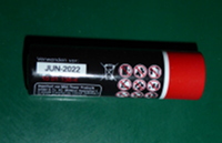 |
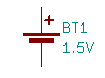 |
BT1 | 1.5V |
| Inductor | 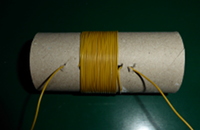 |
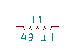 |
L1 | 49 µH |
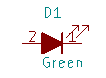
| LED | 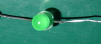 |
 |
D1 | Green |
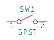
| Switch | 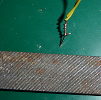 |
 |
SW1 | SPST (simple on/off switch) |
A few comments on the parts and the symbols:
- The plus ($+$) symbol on the battery corresponds to the nub on the top of a dry cell. That’s the positive terminal.
- The number of loops in the inductor symbol has nothing to do with the number of turns on the real inductor.
- The flat side on the LED corresponds to the bar on the LED symbol (pin 1.) Current flows when pin 2 is at a higher voltage than pin 1.
- The switch used in the simple booster doesn’t look much like a normal switch, but it does work like one. It opens and closes the circuit just the same, despite being made of a piece of wire and a file.
Now here’s the simple voltage booster drawn as a proper circuit diagram:
| Booster circuit diagram |
|---|
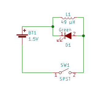 |
On the face of it, that can’t work.
- The LED is shorted by the inductor.
- The LED is pointed backwards - it has the bar towards $+$ and the other end towards $-$ which is the opposite of the direction it should be.
When the switch is closed, current flows through L1 (the inductor) and just goes right past D1 (the LED.) No current will go through the LED - the LED is backwards so current can’t go through it, and the inductor is just a length of wire.
Well, that’s no surprise. We saw that while playing with the simple booster the last time around. You touch wire to the file, and nothing appears to happen - the LED does not light up.
Something does happen, though. The wire in the coil doesn’t act the same as a straight piece of wire.
When current flows through any wire, it makes a magnetic field around the wire. When the wire is wound up into a coil, it makes a much stronger magnetic field.
If you have a magnetic compass handy, you can prove this to yourself. Place the magentic compass next to the coil, and operate the switch on the simple booster. The needle of the compass will go crazy. Connect the wire to the file and don’t move it, and the compass needle will turn to point at the coil and stay put.
So, the whole time when it looked like nothing was going on, something was going on. The current was making a magnet out of the coil.
The current flow looks like this when the switch is closed:
| Booster charging |
|---|
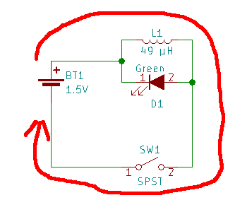 |
Now, the thing about inductors is that it takes energy to make them into a magnet. The more turns of wire in the coil, the bigger the magnet, and the more energy it takes to make the magnet. But, it can only hold the energy as long as you maintain the current through the inductor.
If you stop pushing current through the inductor, then the inductor stops being a magnet. To stop being a magnet, it has to get rid of the energy that was stored in it. It does that by (in effect) becoming a sort of small battery. It delivers current instead of just passing it.
The current that flows when the inductor sheds its energy flows in the same direction as the current that charged the inductor to begin with.
If you stop the current flow from the battery, then the current flow looks like this:
| Inductor wants to shed its energy |
|---|
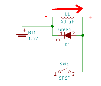 |
Another thing about inductors is that they try to keep the same current flowing after being disconnected as was flowing during the charge up. The voltage doesn’t matter. The voltage will keep going up until it is high enough to make the current flow the same as before.
Now, that’s handy. The whole problem was that we need a higher voltage than the battery can supply to make the green LED light up. The coil does it for us, just as soon as we stop feeding it current.
It takes in current from a low voltage source, and can release it as a higher voltage but at the same current.
This does not mean we’ve gotten energy for free. We’ve stored a little energy, and are releasing it in a slightly more convenient way. That’s all.
We put in current at low voltage for a short period of time, and get the same current out at a higher voltage for a shorter period of time.
That’s conservation of energy.
\[Current * Voltage * Time = Energy\]You can juggle those three factors any way you like, but the energy you’ve got is all you’ve got.
In the inductor, the current is fixed during discharge (the inductor sees to that.) The stored energy is fixed - it depends on the size of the coil and the current, and those are fixed values (more or less fixed - they depend on the battery and the resistance of the wires and switch, and those stay pretty much the same.) All that’s left is voltage and time. Since the voltage has to go up from 1.5V (battery voltage) to 2.2V (LED voltage) before current can flow, the time that the current can flow must be shorter. (That product of current, voltage, and time must give the same value as the stored energy.)
Now, here’s what the current flow looks like when the voltage from the inductor has risen enough for the LED to conduct:
| Booster lighting the LED |
|---|
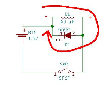 |
Notice the little $+$ and $-$ marks I put by the inductor? Follow the wires, and you’ll see that the LED is properly wired to conduct current from the coil (though not from the battery.) For a short moment after the switch is opened, the inductor delivers current at a slightly higher voltage to the LED. The coil is in effect a weak battery that powers the LED for a short moment.
And that’s it. Inductors just want to maintain the same flow of current at all times. If you stop the current, they will jack up the voltage until something gives and the current can flow again.
The whole cycle looks like this:
- Close switch
- Inductor stores energy in its magnetic field
- Open switch
- Inductor pushes the voltage up to release its energy
- Voltage goes above what the LED requires, and current flows
- The LED lights up
- The inductor sheds all of its energy through the LED
- The LED shuts off for lack of current
- Repeat
In a real boost converter the switch is operated electronically. It switches on and off at a controlled rate to provide a steady output. There’s usually a capacitor across the output to smooth it more and make a nice, steady DC rather than the scratchy pulses that the simple booster provides.
For the simple booster, it was more important to make it simple than to make it conventional. It had to be simple to build, and simple to explain. Every additional part just obscures the basic principle.
Do you doubt that the coil makes all the difference?
Well then, tear the cardboard tube out without disconnecting the wires. Untangle to coil until you have just one long loop of wire.
Now, see if you can get the LED to light up.
About that inductor:
You may have noticed that I gave a value of 49 micro henries for the coil used in the simple booster. That is the calculated inductance given the wire I used (0.6mm diameter of the copper plus insulation,) the diameter of the cardboard tube (42mm) and the permeability of air. The value was chosen on purpose. There is a commercial IC that does the same thing as the simple booster. It uses a 47µH inductor and a single AA cell. I knew that the combination of inductance and available current would provide enough boost to work without a risk of burning up the LED.
The exact value isn’t critical, and it is doubtful that a hand wound coil truly hits that 49µH. It doesn’t matter, though. It’s close enough to work, and could probably be several times higher without being a problem or several times smaller and still make enough light to see.
If you are an engineer, you can calculate that kind of thing. If you are a hobbyist like I am, you use shortcuts rather than slogging through a bunch of calculations to get an exact number.
(I went back and recalculated the size of the inductor. Turns out I was off by quite a bit.)
(If you are interested in what gave me the idea for this circuit and why the booster is built like it is, have a look here.)