Photographing the invisible - the very first steps
Is this even worth trying?
RF camera and radio telescope - Table of Contents
As I mentioned in my last post, I decided that I would rather tell the story of the microwave camera more or less the way it happened.
The first step towards building the microwave camera was to see if there was really even any point to it.
The cheapest way to get started was to buy a low noise block (LNB) from the local hardware store, and a satellite finder kit that had a meter instead of a beeper.
Here they are together:
| The dynamic duo - sat finder and an LNB |
|---|
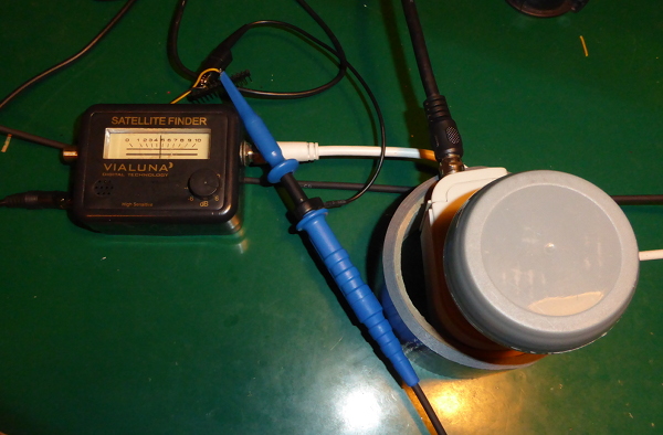 |
Forty years ago, you’d have had to be a microwave engineer and shell out a lot of bucks to get that hardware. That’s a dual band, switchable polarity low noise converter with performance specifications you couldn’t have gotten back then for love or money. The other gadget is an RF level detector with a display meter - a professional engineer would have used a spectrum analyser, and an amateur would have been hard pressed to make a level detector that would work reliably at the 2.5GHz bandwidth required.
Now, everybody and his dog’s got an LNB on a satellite TV dish and “Thumbs McGoober” at the local TV repair and installation shop has a simple, reliable satellite detector.
I picked the satellite finder with the meter for a very simple reason: When you open it up, it is blinking obvious where to pick up the voltage that represents the RF signal strength.
Once I had those two together, I took them out in the backyard and pointed them at things. Trees, bushes, the frame of the swingset, the sky, the ground, etc. It was soon obvious that it could detect RF coming from different places. Trees and bushes (and the ground) showed higher readings than the sky. The metal of the swingset frame showed a lower reading than the bushes, but higher than the sky.
I’m not going to try to replicate that here. If you want to, you can pick up the hardware cheaply enough and give it a try.
After that, I took the stuff back in the house and opened up the sat-finder. I followed the wire from the meter back through the PCB to the point where a relative of the ancient 1458 opamp was used to amplify the rectified DC after the RF detector. A couple of wires and a hole in the housing, and I could connect it first to my oscilloscope, and later to an Arduino.
I found I could get clear signals just from passing my hand in front of the LNB:
| Handwavium |
|---|
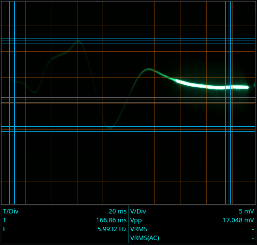 |
That’s just passing my hand in front of the business end of the LNB. The whole “incident” lasts about 160 milliseconds. The voltage measured is rather small (17 millivolts peak to peak) but just (barely) detectable with the ADC of an Arduino (its 10 bit ADC and 5 volt reference gives 5 millivolt resolution.)
That was pretty much that. The meter movements that I saw outside when looking at random objects were bigger than the meter movement from passing my hand in front of the LNB, so it seemed obvious that there was enough microwave radiation all around to make pictures of - and since different objects showed different readings, it also seemed obvious that I could make images of different things.
While playing with the satellite finder in my work room, I also discovered that fluorescent lights broadcast an amplitude modulated signal that the LNB could detect:
| Fluorescent light signal |
|---|
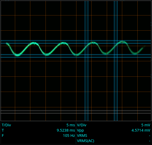 |
The satellite finder is really nothing more than an AM demodulator that works up to 2.5GHz. The LNB converts the 12GHz signals it picks up down to 2.5GHz for the receiver to use. The sat-finder just rectifies that signal and drives the meter. Well, a rectifier is also an AM demodulator.
The fluorescent light over my workbench amplitude modulates a 12GHz signal with a harmonic of the 50Hz line frequency. It’s not that it intentionally generates that signal, but the discharge through the mercury vapor seems to generate a lot of high frequency noise. The line frequency gets into it because the discharge is started and stopped 50 times per second due to the AC. Why I get mostly the 100Hz harmonic is a puzzle - probably has to do with the electronics driving it, but I’m not interested in that enough to find out what is really going on. Maybe one of ya’ll would like to take a stab at it?
At any rate, those first experiments made it clear that there was something there and that it could be detected with relatively simple equipment.
With a workable detector in hand, I set about planning the hardware for the camera.
I’ll tell you about how the hardware was “designed” in my next post.