Photographing the invisible - building the hardware
Hardware store stuff - not the electronics.
RF camera and radio telescope - Table of Contents
After I determined that there was actually something worth photographing at 12GHz, I started in on figuring out how to build a steerable mechanism to aim a satellite dish.
The obvious solution would have been to use servo motors or stepper motors. Those are the go-to motors for precisely controlled motion.
Problem is, they are more complicated than I wanted to deal with - I’m even less of a mechanical engineer than I am an electrical engineer. Whatever I build has to be simple. Using normal servos or stepper motors would have required building something to convert the rotation to a linear motion.
The solution I chose was RC servo motors. Those motors are easy to control with a pulse width modulation signal, and it is fairly straight forward to use them for linear motion.
I looked at several of them in various online catalogs, and simply picked the beefiest ones I could get for a reasonable price. The first pair were analog servos rated for 18 kgcm of torque. Having handled satellite dishes before, I knew that 18kgcm was not adequate. I also knew that I could use lever action to “gear them down.” Less range of motion for more oomph - and slower, of course.
I mounted one servo on my workbench with the horn attached to a piece of wood that was hinged to the workbench at one end - literally hinged, with a hinge intended for a cabinet door. With a servo tester to control the servo, I moved the servo up and down the length of the stick, and checked to see how well the servo could lift the wood with me pushing down on it about as hard as I thought it would take to move the satellite dish. I figured I needed to arrange it so that the full 120 degree range of the servo was reduced to about a 20 degree range of motion on the driven stick.
That’s the ratio I used to build my first steerable satellite dish, and the second as well since it worked out just about right.
Here’s the first version:
| Original microwave camera |
|---|
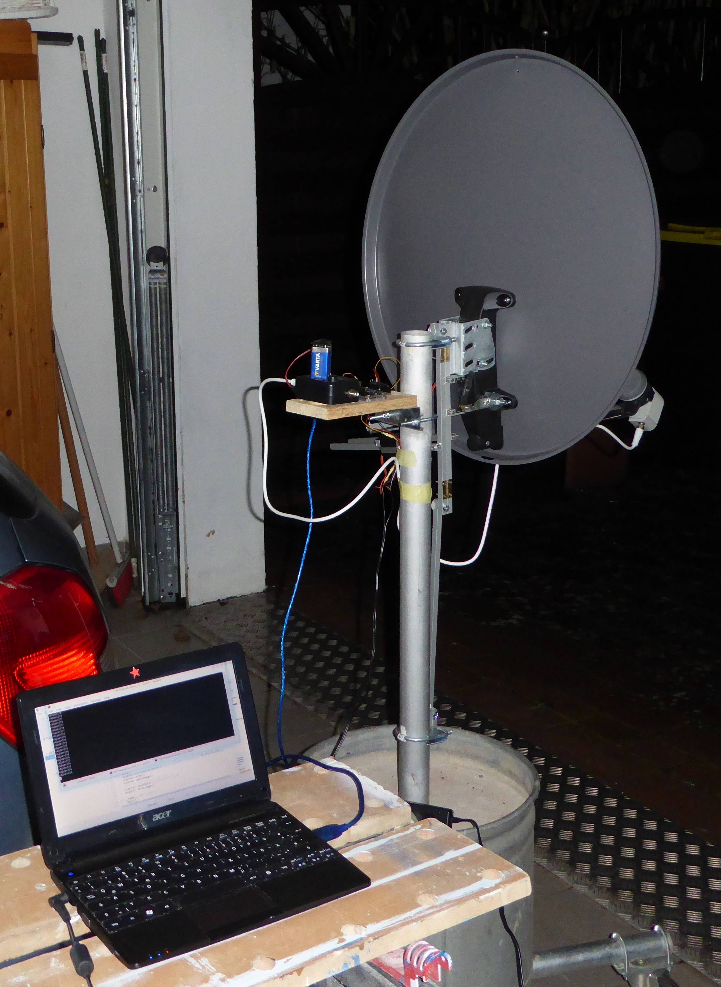 |
If you look closely, you’ll see there are really two cabinet hinges in there for the left/right motion. The up/down axis uses the original mounting hardware from the satellite dish. It worked, and it moved, and it obeyed commands through the Arduino there by the satellite finder.
I used it to make several images. I kind of bungled the lever lengths, though. All the images are sort of mashed - they aren’t as tall as they should be.
This is the very first complete image I made with that set up:
| First image from the microwave camera |
|---|
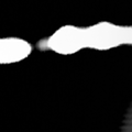 |
Those are the Astra satellites, visible straight south out of the door of my garage. I got lucky in hitting them on the first try - I looked up at the satellite dish we use for TV reception and kind of eyeballed it. Got it close enough for the satellites to be in the 20 by 20 degree range of motion of the camera.
That version didn’t last long. The axles weren’t smooth enough, and the lever ratios were wrong. It tended to get stuck at spots and skip a bit. Also, it was mounted on a stand that I originally made for a large shade umbrella - once summer rolled around I had to take my gadgets off so the stand could be used out in the yard.
Having gained a little experience in how it should all work together, I built this second version:
| The improved microwave camera |
|---|
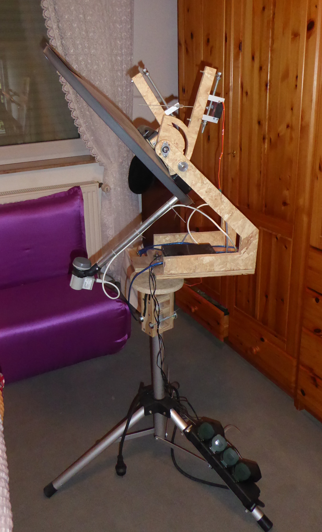 |
I sketched it out, and ordered a bunch of bearings and an 8 mm stainless steel rod to use for axles. I had some OSB sheets laying around from the time my son and I installed a sort of attic in the garage. That stuff is pretty easy to work with, and fairly stable (it doesn’t shrink or expand much.) The hardest part was cutting the steel rods for the axles. After half an hour with a hacksaw had done nothing but polish the stuff, I got out a bench grinder and mounted a diamond cutting wheel in it - that took care of things pretty quickly.
The servos are mounted so that they can be adjusted for motion range and lever ratio. The parts for the vertical and horizontal motion are layed out so that was almost impossible for the ratios to be wrong - this setup has the proper aspect ratio so my images aren’t squashed.
I’ve posted all of the drawings I used in making that to a github repository. I think everything is there. I don’t remember if I made drawings for everything, or if I put all of them in the same folder on my computer.
I have an odd style of making things. I make drawings in Inkscape which I print out and glue or tape to the material I’m working with. There are center markings for holes, and the hole size is usually marked as a ring around the center. For my way of thinking, it is usually obvious what to cut out or what the outlines are. If not, well, you can always open an issue on the repository and ask for a clearer drawing. It should be fairly easy to modify things to hold just about any typical household satellite dish.
I bought the stand. It cost like 15 bucks from Amazon. I couldn’t build anything that cheaply.
You may notice that the upper brackets are built so that the dish can tilt way down. That’s necessary. The satellite dishes are offset - when it looks like they are pointing straight ahead, they are actually “looking” up at some 10 to 20 degrees. By tilting way down, the dish can be made to really look straight ahead.
Something else that’s not immediately obvious is that there is a manual adjustment for the up/down aim. The servos can only move it some 20 degrees, but I want to be able to make images of the sky.
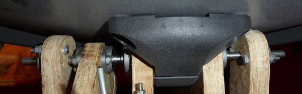
Here’s the vertical adjustment:
| Upper adjustment |
|---|
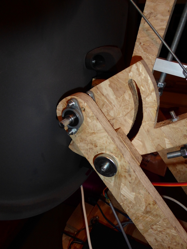 |
That knurled knob and the curved slot let me rotate the dish to point up and to some extent back - the camera can look straight up into the night sky. Look closely and you’ll see where I drilled a couple of holes wrong.
I did something similar for horizontal rotation, though I most often just pick the whole thing up and rotate it rather than using the knobs.
| Lower adjusment |
|---|
 |
The servo mounts are made so that I can (somewhat) easily change the lever ratios:
| Servo mount |
|---|
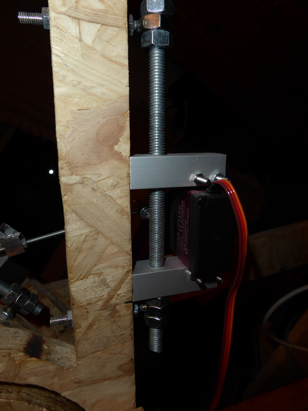 |
Just loosen the two nuts on the back of the wooden support arm then slide the servo up or down. The horizontal servo is made the same. The servos are actually screwed to lengths of 10mm square aluminum tubing. More stuff I had in the junk box in the garage.
The servo linkage is mostly hand made:
| Servo linkage |
|---|
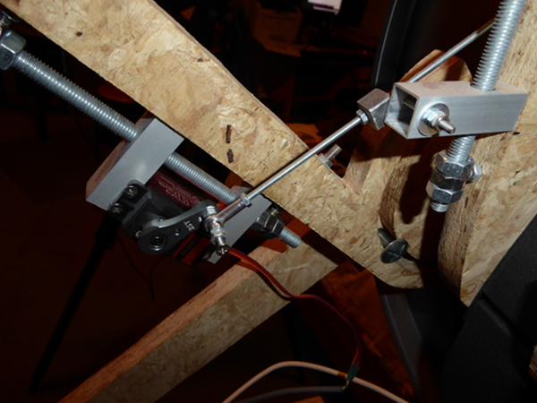 |
I left the long threaded rod long on purpose - if I change lever ratios I have to adjust the linkage to fit. That’s also why that block the threaded rod goes through is there. If I’d have used standard swivel ends on it, then the linkage would have to be rebuilt any time I change lever ratios. That ugly looking block is threaded and the rod goes through it - that lets me adjust the linkage. This is the linkage for the vertical servo - the linkage on the horizontal servo is identical.
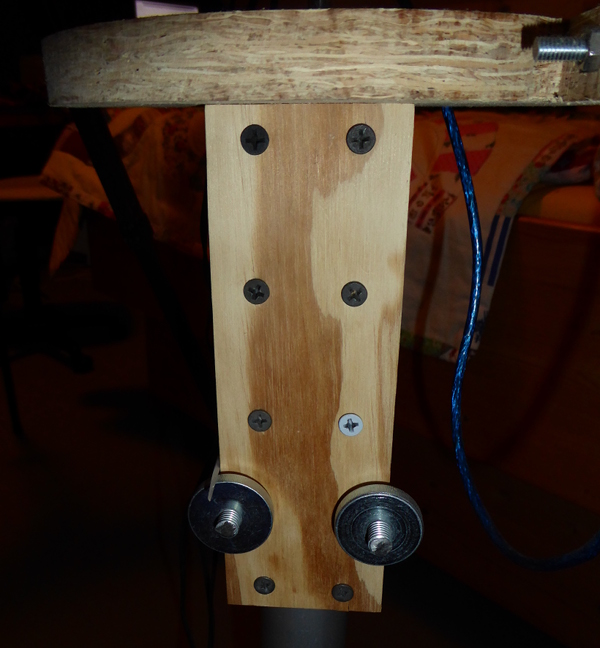
These are the bearings for vertical motion:
| Vertical bearings |
|---|
 |
And the horzontal ones:
| Horizontal bearings |
|---|
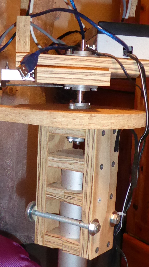 |
I used self centering FL-08 bearings. The self centering part kind of forces me to have the bearings in pairs. There’s 10 of them in all. This version of the microwave camera moves smoothly when the servos drive it.
Something I want to mention is that I gave the vertical servo mounting a lot of thought. The way it is arranged, the dish lowers to a resting position if the servo shuts off. The software starts up expecting both servos to be at a specific zero position. This arrangement I used makes sure that the vertical servo is always in position when the power comes on. That’s kind of necessary. The horizontal one can be moved by hand to the correct location before power on, and it will stay there. The vertical one needed to always revert to down so that I don’t have to hold it in place while turning on the power.
I think that’s about all the interesting bits I have to tell about the mechanical parts.
Next time around I’ll explain a bit about the electronic parts.