The Telequipment D43 high voltage replacement board
What to do when your D43 explodes.
My Telequipment D43 projects - Table of Contents
I’ve mentioned my old Telequipment D43 before. I’ve written several posts about the D43 oscilloscope software that I wrote, and the camera and mount I built to go with the software.
I’ve also mentioned it in the series I wrote about some experiments with voltage doublers and multipliers.
The wrap up post of the voltage multiplier series is what brings me back to the D43 this evening.
In that post, I mentioned that I first got interested in voltage doublers because the high voltage section of my D43 exploded on me - twice. The high voltage section of the D43 uses a Greinacher voltage doubler to convert 1200VAC to 3.2kV DC, so I learned a bit about voltage doublers to fix my oscilloscope.
I was contacted just recently by someone else whose D43 exploded in just the same way mine did. It seems to be a common problem with these scopes. Or maybe not. Maybe we’re just the last two people on the planet who still use such ancient scopes.
In any case, I was asked how I fixed mine. Or rather, what parts I used and whether a certain other set of possible replacements would be acceptable.
First I’m going to show how I fixed mine and what parts I used, then I’m going to check if the suggested replacements would be suitable.
To get started, here’s a section of the powersupply schematic for the D43 showing the parts that exploded.
| D43 high voltage supply |
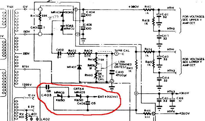 |
C403 is the one that literally exploded. The first time (about 20 years ago,) it blew up and knocked a (paper) notebook off the top of the scope. The capacitor also caught on fire. The whole incident was very exciting.
Back then, I had a spare high voltage board from a scrapped D43. I just swapped it out and went on with what I was working on.
The second time it exploded was just a few years ago. I heard the oil in C403 start to boil, and unplugged the scope fast enough to prevent a real explosion. C403 just sort of went “Foop!” and poured its greasy guts out and made a mess.
I thought I had another good spare, so I swapped it out and - no go. The “good” spare was shot, too.
Both times, it wasn’t just the exploded capacitor that died - both diodes and the other capacitor seem to go out when the capacitor pops.
You can’t just replace the one part, you have to replace all the parts in that section.
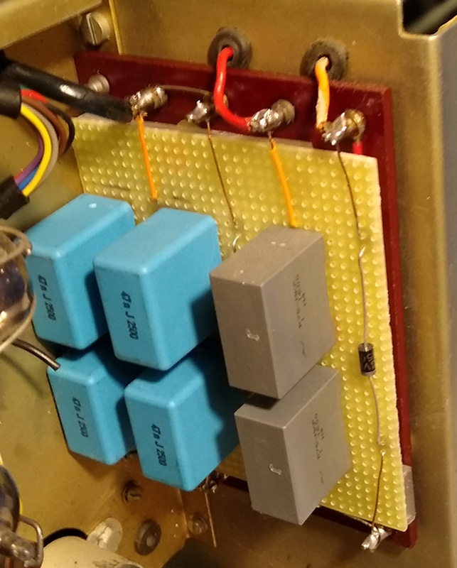
This is the board I built as a replacement:
| D43 high voltage supply replacement |
 |
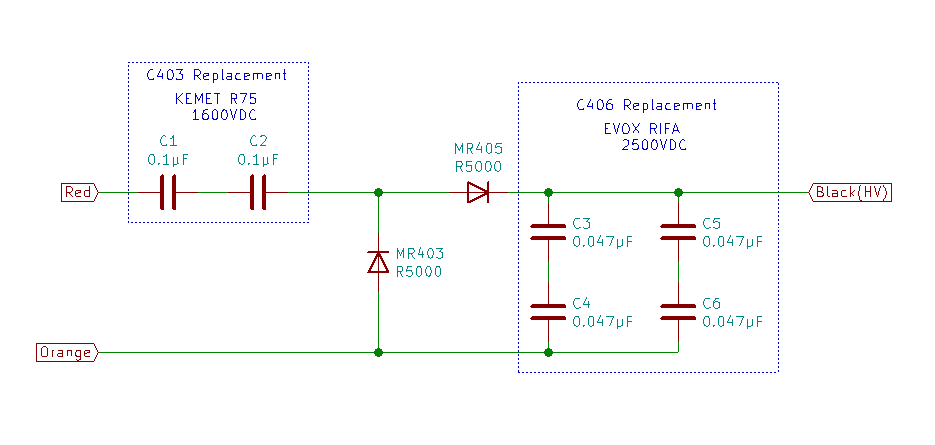
This is the schematic of the replacement:
| D43 high voltage supply replacement schematic |
 |
Here are the datasheets of the parts I used:
| Quantity | Part designator | Value | Datasheet |
|---|---|---|---|
| 2 | C403 | 0.1µF | KEM_F3106_R75 |
| 4 | C406 | 0.047µF | EVOX RIFA PHE450 |
| 2 | MR403 MR405 | R5000 | Rectron R5000 |
You’ll notice I used multiple capacitors rather than simple replacements. There’s good reason for that. Take the PHE450 capacitors. They are rated for 2500 VDC and cost about 3€ each. That’s about the highest voltage rated part you can get. The capacitors in the high voltage section have to be able to withstand at least 3200VDC. Capacitors rated above 3000VDC aren’t well stocked at most suppliers, and they usually cost a lot more than the lower rated parts. At the time I built this thing, I couldn’t locate parts rated for more than 3200VDC that could be delivered quickly and not cost me an arm and a leg.
I don’t remember why I used two different combinations to make two copies of the same value part. I think I ordered parts and built one, then found I needed to replace the other as well and had to use different parts because the others weren’t available anymore.
In both cases, I used two in series to get the needed voltage rating. The R75 parts are 0.1µF, so two in series gives the needed 0.05µF. The PHE450 parts are 0.047, so I put two in series for the voltage rating and two blocks of two in parallel to get the capacitance back up.
The R5000 diodes are simple rectifier diodes with no special qualifications except that they have a peak inverse voltage rating of 5000VDC. Any replacement you use will have to be rated for well over 3200VDC.
I won’t sketch out how I wired them on the perf board. I think that’s pretty straight forward.
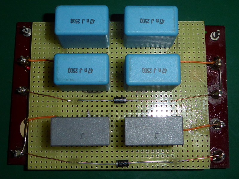
I will show you how mine is made:
| D43 high voltage replacement photos |
|---|
 |
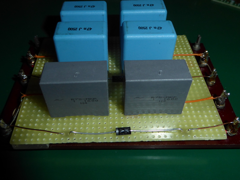 |
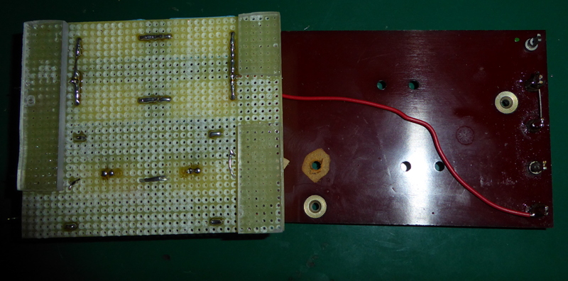 |
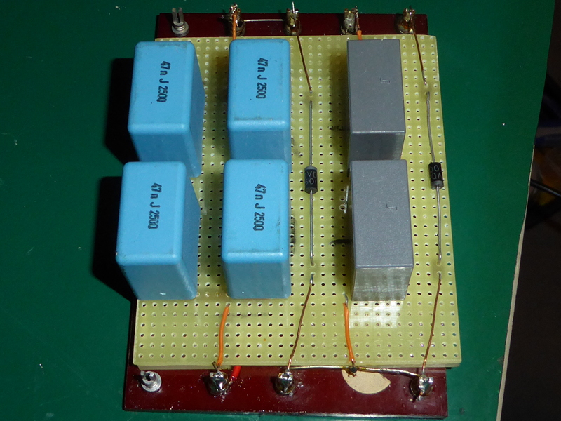 |
If you look closely at the picture of the bottom of the perf board, you’ll see that it actually had solder pads on all the holes. I removed them all by hand with a drill bit, except for the ones I needed to solder the parts into place. I had forgotten about that. 3000 volts can easily jump a millimeter, and if things are dusty or damp even more. You’ll need to make sure there’s adequate clearance around all of the connections.
Now, on to the request I received.
I was asked if the following parts from Mouser would be suitable for a replacement high voltage section for a D43.
| Part | Datasheet |
|---|---|
| Capacitor | WIMA FKP 1 0.015µF |
| Diode | GI250 |
The capacitors are rated for 6000VDC, so that’s fine. Currently, Mouser only has them in 0.015µF, though. That’ll mean using three of them in parallel to get close to the 0.05µF of the original. The brand might be a problem. I’ve been told that Wima isn’t the best. That may be true. It’s also a pretty good bet that even a “bad” modern part is better than the original was when it was new.
Squeezing three capacitors in parallel in the available space might be fun, but the Wima parts are smaller than the ones I used. They ought to fit, but you might have to get creative about how you lay them out.
The GI250 diode is rated for 4000VDC PIV, which is adequate. The original K8-50 diodes were rated for 3200VDC PIV, which is right exactly at the DC voltage this thing is supposed to generate. That might have contributed to the explosions. I’ve never figured out if one of the diodes went out and took the capacitors with it, or if the capacitor died first and took the diodes with it.
You’ll need to make sure to get the GI250-4, though. The -4 means 4000VDC rated. There are lower rated GI250 diodes available. Don’t use them. The next down is the GI250-3 that’s rated for 3000VDC PIV. That’s too low.
In summary, the selected parts should work though it might be challenging to get them in place.
Do be careful when reassembling the scope. One of the screws can get very close to the high voltage terminal. If it is too close, then the high voltage will arc across when the scope is running. It makes a very loud snapping noise, and I can’t imagine it does any of the parts good.
| Here be dragons |
|---|
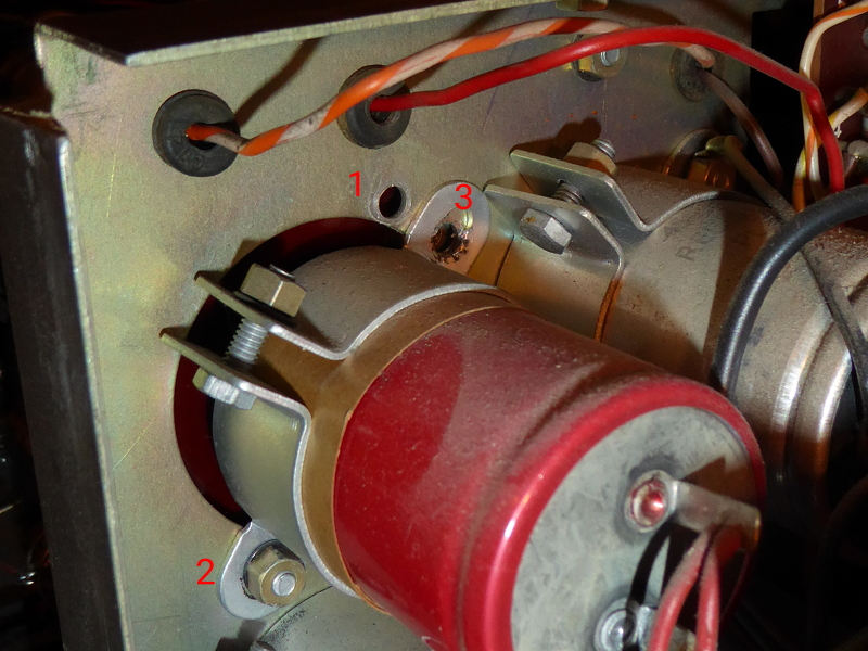 |
The hole marked “1” is where that big red capacitor is normally mounted. It had a screw with the head under the high voltage section and the nut in back like the spot marked “2.” With that screw installed in “1” I found that the high voltage would occasionally arc over to ground on the screw head. I removed it, and used just the hole marked “3” to hold the capacitor in place. That screw goes in from the back and screws into a captive nut on the back of the high voltage board. It holds everything together just fine even though the capacitor is a little off center.
Over the years, I’ve collected a few documents about the D43 and the K8-50 diode. I don’t remember where I got them.
| Telequipment D43 documents |
|---|
| Manual |
| Type J vertical amplifier manual |
| K8-50 diode |
If you’ve found your way here, and the tips above have helped you get your old Telequipment D43 (or other analog scope) running again, why not take a look the D43 software and make a digital storage oscilloscope out of your old analog friend? The D43 software doesn’t just make pictures, it also digitizes.
Leave a comment below and let me know if you’re keeping an old oscilloscope running.