Voltage multipliers - Part 6 Impedance and current in voltage multipliers
Where did my voltage go?
Voltage multiplier experiments - Table of Contents
Figuring out how the capacitance relates to the impedance of a voltage multiplier.
Back in part 3 of this series, I mentioned that the impedance of the capacitors influences the output current of a voltage multiplier. To be specific, the impedance of the capacitors is the limit on how much current you can draw through a voltage multiplier. This came up while looking at the full wave Cockcroft-Walton multiplier, but it applies to the half wave Crockcroft-Walton as well. It applies to single stage as well as multi-stage multipliers.
Most of the multipliers and doublers I’ve looked at were built using 100nF capacitors. A 100nF capacitor has an impedance of around 31k ohms at 50 hertz.
For comparison, I’m going to build a Greinacher doubler using 10nF capacitors. They have an impedance of around 310k ohms at 50 hertz.
That kind of thing goes pretty quick. The voltmeter says the output is 31.3V DC. A quick check against the Greinacher with 100 nF capacitors (yes, I have them all laying here on my workbench) shows the output at 38.6 VDC. Even with just the voltmeter as a load, the 10nF Greinacher has a lower output voltage.
If I “load” either of them with my oscilloscope, the output voltage drops.
Just how darned much of a “load” is my oscilloscope, anyhow? It’s supposed to be high impedance - the probes are rated 1M ohm.
For a given frequency (50 Hz,) we can pretend the capacitors are resistors and use Ohm’s law and treat the capacitor and the oscilloscope probe as the two parts of a voltage divider.
I’m going to compare the impedance of my scope to the impedance of a 10nF capacitor.
Like this:
| Oscilloscope probe impedance measurement |
|---|
|
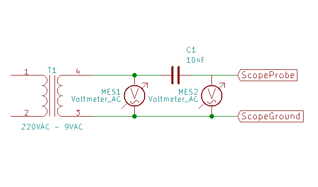
The voltage difference between MES1 and MES2 tells me the voltage drop across C1. From that I can calculate current. With the current and the voltage from MES2, I can find the impedance of my scope.
The easiest way to do that is just to measure the RMS voltage with the scope directly across the transformer, and then measure the RMS voltage with the probe on the other side of the capacitor.
| MES1 | MES2 | Difference | Capacitor Impedance | Current | Scope Impedance |
|---|---|---|---|---|---|
| 11.4V | 10.7V | 0.7V | 318k ohm | 0.025 mA | 4.86M ohm |
Well, that’s more than I expected. From the way the voltage from the multiplier dropped, I was expecting something much lower.
What’s the impedance of the 10nF Greinacher, then?
I’ll use my multimeter to measure the unloaded voltage and the voltage with a known load. The “known load” is a 474k ohm resistor I found in the bottom of the junk drawer. It measures at 462k ohm.
| Unloaded | Loaded | Difference | Load Resistance | Multiplier Impedance |
|---|---|---|---|---|
| 30.7V | 7.4V | 23.3V | 462k ohm | 1.45M ohm |
That looks to me like the impedance is about four times the impedance of the capacitors used.
Now I’ll see what the 100nF Greinacher looks like.
| Unloaded | Loaded | Difference | Load Resistance | Multiplier Impedance |
|---|---|---|---|---|
| 38.1V | 24.0V | 14.1V | 462k ohm | 271k ohm |
271k ohms isn’t four times the impedance of a single capacitor. What ever the rule is, it isn’t as simple as multiplying the impedance of the parts.
Well, then I’ll just have to build more doublers and draw a curve. I have 1µF and 10µF capacitors here, so I’ll just build Greinacher doublers out of them and see what impedance I can measure from them.
Here’s a summary:
| Capacitance | Capacitor impedance (50Hz) | Unloaded | Loaded | Difference | Multiplier Impedance |
|---|---|---|---|---|---|
| 10nF | 318k ohm | 30.7V | 7.4V | 23.3V | 1.45M ohm |
| 100nF | 31.8k ohm | 38.1V | 24.0V | 14.1V | 271k ohm |
| 1µF | 3.18k ohm | 39.7V | 37.2V | 2.5V | 31.1k ohm |
| 10µF | 318 ohm | 39.0V | 38.5V | 0.5V | 6k ohm |
Loading all of that into the Libre-Office Calc program (and ignoring the 10nF row because its output is low even unloaded,) I get the following plot:
| Greinacher doubler output impedance vs capacitor impedance |
|---|
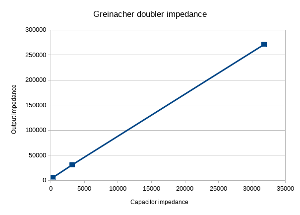 |
Looks nice and linear. Calc tells me that that the slope of the line is 8, and the intercept is 3827.
To figure the output impedance, you take the impedance of a single capacitor and multiply it by 8 then add 3827 ohms.
Lets see how that works. I’ll make 5µF capacitors out of some 10uF capacitors. That’ll give me an impedance of 636 ohms at 50Hz. That ought to work out to a total impedance of 8*636+3827= 8.9k ohms. The loaded output voltage ought to be around 38.3, assuming 39.0V as input.
Here are the real measurements:
| Unloaded | Loaded | Difference | Load Resistance | Multiplier Impedance |
|---|---|---|---|---|
| 39.4V | 38.7V | 0.7V | 462k ohm | 8.4k ohm |
Close enough.
That factor of 8 makes the selection of the capacitors an important part of designing a Greinacher multiplier. It also makes the working frequency important.
At 1kHz, the impedance of a 1µF capacitor drops from 3.18k ohm to 159 ohms. 10kHz, and you are down to 16 ohms for the same capacitor.
OK, so how much current can you get out of Greinacher multiplier?
Taking the 10uF multiplier, I get about 20 mA short circuit current. I don’t think the values are quite right, but they do show that you aren’t going to get a lot of current through a voltage multiplier. Calc wasn’t joking about that intercept. That’s your final limit. You can’t get below it.
So where does that intercept come from? I suspect it comes from the diodes. I mean, there isn’t really much left once you’ve accounted for the capacitors. The transformer is good for a couple of hundred millamperes, so it isn’t the limit. All that’s left is the diodes.
If the intercept comes from the diodes, then a set of two stage Cockcroft-Walton multipliers ought to show a factor of 16 times the impedance of a single capacitor plus twice the intercept (so, about 7.6k ohms.)
Here’s the numbers for a series of two stage Cockroft-Walton half wave multipliers:
| Capacitance | Capacitor impedance (50Hz) | Unloaded | Loaded | Difference | Multiplier Impedance |
|---|---|---|---|---|---|
| 100nF | 31.8k ohm | 23.7V | 12.3V | 11.4V | 428k ohm |
| 1µF | 3.18k ohm | 53.5V | 42.0V | 11.5V | 126.5k ohm |
| 10µF | 318 ohm | 62.0V | 59.0V | 3.0V | 23.5k ohm |
Now what does Calc say? Calc says slope of 36 and intercept of 15850. How does that compare with the measured values? Looking at just the 1µF, I get 130k ohms by the Calc values. For the 10µF multiplier, I get 27.3 k ohms.
That’s not anywhere close to what I expected. I expected the intercept to double, but it went up by a factor of 4 - and I sure as heck didn’t expect the impedance to go up that steeply. From factor of 8 to 16, but not to 36.
Hmmm. More mysteries, and I haven’t even solved the one I wanted to yet. I’ll have to look into the intercept and the impedance progression another time.