A hat full of electrometers - Testing the first electrometer
A miniature, gold plated electrometer.
A hat full of electrometers - Table of Contents
My daughter originally asked to have a string of commercially made LED lights (with little pumpkins) put on a hat as decoration for a Halloween costume. I couldn’t find any that were small enough, so I settled in to make something different but still in keeping with “spooky” and “hat.”
What I’ve come up with is a string of LED electrometers to go on her hat.
A fellow named William Beaty described a simple LED electrometer back in 1987.
This is his design, made of parts that were available at Radio Shack back then:
| William Beaty’s electrometer |
|---|
 |
I built one years ago, and still have it in my collection of junk to play with:
| JRE’s electrometer built to William Beaty’s schematic |
|---|
 |
There’s really nothing special about any of the parts, except that it is difficult to get the MPF-102 these days. I built mine with a 2N5484.
For my daughter’s hat, I decided to get a little fancy.
I designed a slightly different circuit, using stupidly bright orange LEDs (ersatz pumpkins.) The bright LEDs let me put a fairly large resistor in series with the whole thing and reduce the current while still having the LEDs bright enough to see from a distance.
Here’s the circuit I settled on:
| JRE electrometer |
|---|
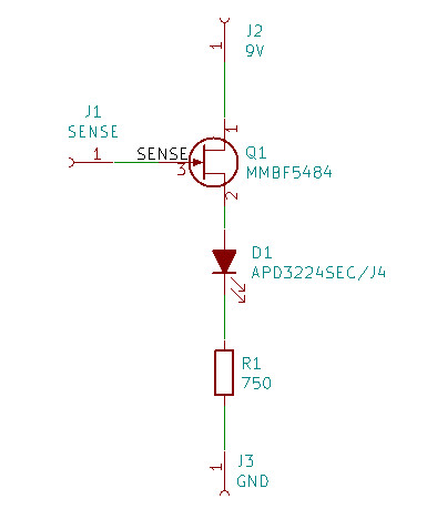 |
Very similar to the original, except it’ll singe your eyebrows off at short range - and only consume 2 milliamperes of current while doing it.
The biggest difference is that LED. The APD3224SEC/J4 is rated for 8000 millicandela at 20 milliamperes. I haven’t been brave enough to light one up at 20mA. The couple of milliamperes I’m feeding it now leave afterimages.
The MMBF5484 is simply an SMD version of the 2N5484 I used in the electrometer I built years ago.
All the parts came in a few weeks ago, and I finally got the PCBs made - the electrometer boards arrived just today. I put one together to make sure everything works according to plans.
Since there will be seven electrometers, but each only draws a couple of milliamperes, I decided to stay with a 9V battery. I had a bunch of electrometer boards made, and a couple of battery boards.
| Electrometer PCBs |
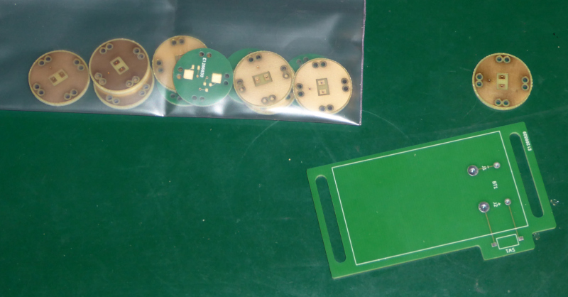 |
That’s one battery board and a baggie full of electrometer boards. I had 10 made because it cost less to have the 10 made than 8. I wanted 7 for the hat and a spare. I got 7 for the hat and 3 spares because it was cheaper. If you look closely, you’ll see I got 11 electrometer boards in all - Eurocircuits usually throws in an extra just in case there’s a problem.
The battery board carries a 9V battery clip and a small switch. The slots are for the cloth hat band. The plan is for the band to go through the slots and then wrap around the battery board with a big knot and bow to hide the battery.
Assembly isn’t especially tricky, except for the LED side. That side is gold plated and doesn’t have any solder mask - the gold is only for appearance’s sake, so it has to be bare so you can see it.
That bare gold makes the front side a little special. I dealt with this before when I made my own cellphone detecting hat band. The same trick that worked back then worked this time as well.
Frog tape.
The stuff you use to tape things off when spray painting also does a dandy job keeping solder from getting where it doesn’t belong.
| Frog taped electrometer |
|---|
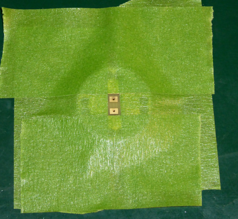 |
The back side doesn’t take anything special at all.
| Finished electrometer board |
|---|
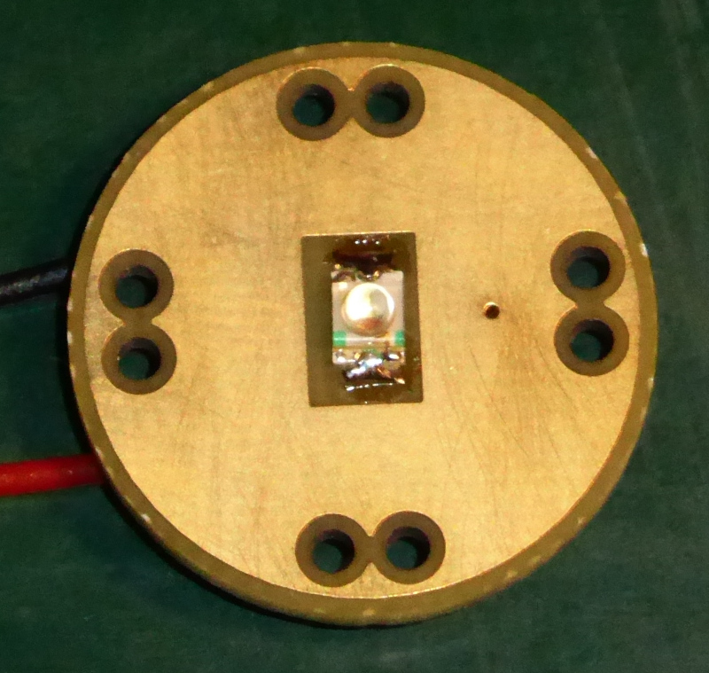 |
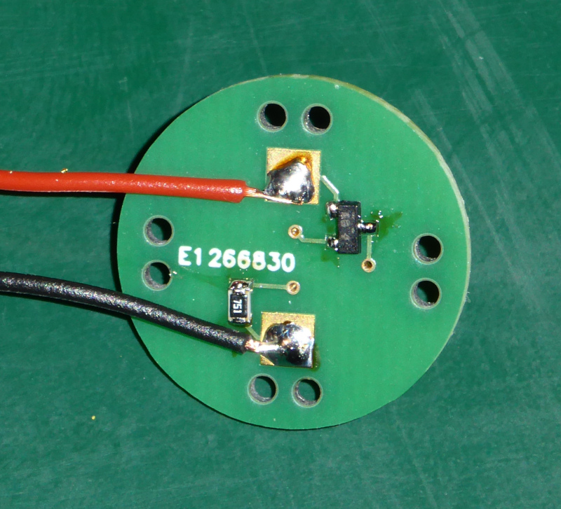 |
I’ll clean the excess flux off of the ones that go on the hat. This one is just a test.
| First test |
|---|
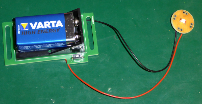 |
Whee! It lights up!
A picture can’t show it reacting to the charge on my chair or the bed (or the cat,) but it does. It also reacts quite nicely from across the room to the charge and discharge of my hand cranked Wimshurst machine.
That’s this thing:
| Wimshurst machine |
|---|
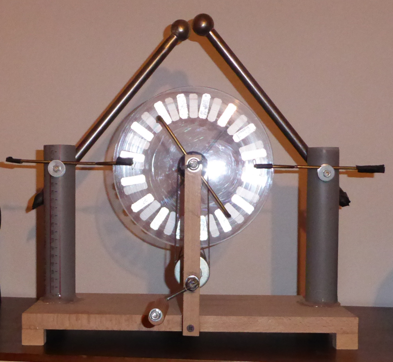 |
It’s hard to see from the photo, but the balls are about 18 millimeters apart. It’ll throw a spark across those 18 millimeters - that’s a little over 50000 volts, given that air has a breakdown voltage of about 3000 volts per millimeter.
Maybe I ought to write that thing up someday.
I figure with seven electrometers spaced around her head, my daughter ought to be a walking electrical field strength display. The LEDs should react to the charge of whatever each one is facing. The “antennas” are slightly directional, and they can’t “see” through her head, so the light display as she moves ought to be interesting. If nothing else the lights will seem to go on and off at random. At best, they might show a consistent reaction to particular people or objects (at least until the charges even out.)
We’ll see.
At any rate, that’s all for today. I’ll assemble the rest when the wire gets here, then I’ll get my wife to help sew the cloth band.
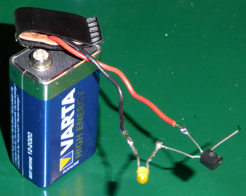
Even on something as supposedly simple as this, I didn’t go straight from idea to PCB. I built a prototype after I got the parts and before I designed the boards.
I “dead bugged” the prototype, and glued it to a piece of cardboard with a long wire to simulate the gold plated area. The prototype worked OK. The real one is better. I was worried that the large area next to a large charge collector (head full of hair and a felt hat) would cause problems, but it doesn’t. The large area for the “antenna” seems to work just fine.
| Prototype |
|---|
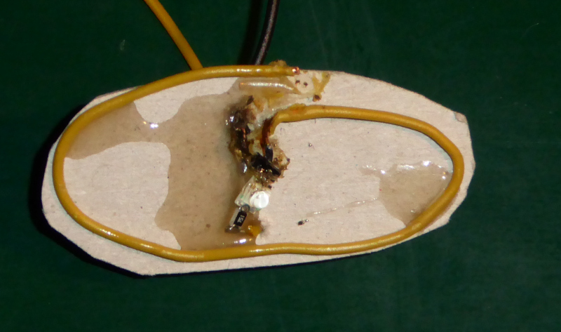 |
It looks rather grotty. I discovered after I glued it to the cardboard that glue is a dandy conductor. I had to burn the glue off the circuit with the tip of the soldering iron. It works, but the burn marks are ugly.